Table of Contents
Advertisement
Quick Links
OWNER'S MANUAL
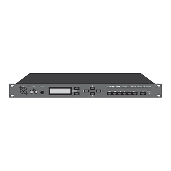
DMM 4650 DIGITAL MESSAGE MANAGER
Description
The DMM 4650 is a signal processor which allows for an universal generation and control of audio signals. Its main
purpose is the installation in electro-acoustic rack systems, but stand-alone applications are possible as well. The
audio signals can consist of alarm, gong, voice messages but also of random combinations of these sources. The pro-
grams were created by Dynacord (preset). Anyway, it is possible for the user (consulting company, etc.) to modify tho-
se programs and store them as user-programs. The audio input can be mixed with the DMM 4650 internally generated
audio signals (e.g. gong signals with announcements), or given out as priority at the audio output (programmable).
The audio quality of the messages can be selected, depending on memory extension and different user requirements.
With maximum memory extension, a total recording time of 16 minutes is possible. Password protection for various
operation levels is provided. For "EASY-USER", the provided operation features are similar to those known from cas-
sette recorders or CD players. The control of the programs is performed via fl oating inputs and fl oating outputs provide
status messages. The priorities and functions of these lines can be programmed individually (Setup). A computer inter-
face facilitates saving and loading of the unit's confi guration and its message data.
In order to ensure functional reliability, self-surveillance and audio data verifi cation are employed. The alarm is ignited
via internal fault-output while all warnings are logged. The DMM 4650 is maintenance-free since no serviceable parts,
batteries or accumulators are to be found inside the appliance.
Advertisement
Table of Contents

Related Manuals for Dynacord DMM 4650


Summary of Contents for Dynacord DMM 4650
- Page 1 DMM 4650 DIGITAL MESSAGE MANAGER Description The DMM 4650 is a signal processor which allows for an universal generation and control of audio signals. Its main purpose is the installation in electro-acoustic rack systems, but stand-alone applications are possible as well. The audio signals can consist of alarm, gong, voice messages but also of random combinations of these sources.
-
Page 2: Table Of Contents
CONTENTS INSTALLATION INSTRUCTIONS ..............FRONT PANEL ....................REAR PANEL ..................... USE OF THE DMM 4650 ..................8 Audio functions ..................8 Control functions ................... Sequence functions ................9 OPERATION OF THE DMM 4650 ..............General ....................10 Stand-by mode ..................10 Password, user password .............. - Page 3 Contrast ....................Backlight ..................... Headphones ..................Priority ....................Password .................... Outputs ....................Bypass ....................Sum gain ..................... init DMM 4650 ..................format Flash ..................Flash space ..................Software ..................... Language ................... Backup ....................Restore ....................RS 232 ....................Clock ....................
- Page 4 FACTORY PRESETS ..................Factory presets, defaults ..............List of trigger signals ................List of factory preset sequences ............List of factory preset gong signals ............List of factory preset alarm signals ............APPENDIX ......................Troubleshooting ..................FAQ’s, hints ..................Examples for alarm texts ..............Block diagram ..................
-
Page 5: Installation Instructions
EU country’s management of WEEE, please contact your local distributor. We are committed to facilitate our own electronic-waste-management-system, for the free of charge return of all EVI Audio GmbH products: Telex, Dynacord, Electro-Voice, Midas Consoles, KlarkTeknik and RTS. Arrangements are made with the dealer where you purchased the equipment from, for the returning of all unusable equipment at no cost, to the factory in Straubing, for environmental protective disposal. -
Page 6: Frontpanel
9. POWER This input can also be used for making announcements. The LED lights whenever the DMM 4650 is ready for operation. In case the LED BLINKS you should contact a DYNACORD service center. 3. PHONES Stereo phone jack 1/4“... -
Page 7: Rearpanel
PORT A-D * optionally retrofi tted All inputs and outputs are provided in 2-pole fl oating de- sign and isolated from the DMM 4650 circuitry and adja- cent lines. 15. PORT D Each input is realized as an AC opto-coupler (AC fl oating Control inputs, trigger outputs and ±24 V DC... -
Page 8: Use Of The Dmm 4650
Use of the DMM 4650 The DMM 4650 can be used in both, incorporated in a rack shelf system or as stand-alone unit. The instal- ler should automate the daily sequences by external control keys, sensors, contacts and the corresponding unit settings. -
Page 9: Sequence Functions
A switch is connected to one of the DMM 4650’s control inputs (A1 - D4). The desired input is selected in the trigger menu. Logic level (high, low), delay, and function (dyn, stc, latch) can be set. The desired sequence (Sxx) gets chosen here as well. -
Page 10: Operation Of The Dmm 4650
Password entry, operation end Pressing any key on the DMM 4650’s front panel, “Password ?” appears on the display. Using the cursor keys you have to enter a 4-digit number and confi rm it with the menu key ok. After entering the correct 4-digit pass- word, the display shows the number of your user level. -
Page 11: Menu Structure
Priorität Priorität Schrittliste Summenpegel Bypass play all priority priority step-list Sum-Gain Abschwächer freigeben sichern sichern Titel init DMM 4650 Attenuator release save savel title init DMM 4650 format Flash Leerblocks sichern Flash Platz format Flash free space save flash space... -
Page 12: Message
Confi rming the menu selection “message” by using the soft key “ok”, the number of the message ap- pears in the display together with its title and playback time (hours : minutes . seconds). The DMM 4650 is now in the recording/playback mode and can be operated using the transport-keys as follows:... -
Page 13: Soft Key "Edt
Soft key “edt” Using the “edt” key in playback mode provides the opportunity to edit and manage your message structure. The keys are used to select the following menu items. Title Confi rming “Title” with the soft key “ok” the selected message’s current name appears on the display. Using the cursor keys lets you enter a name which can consist of up to 8 characters. -
Page 14: Level Adjustment, Record Level
Recording level An integrated, electronic control automatically adjusts the input sensitivity of the DMM 4650’s (Mic, Line, Rec. Inp) inputs. This level setting remains unchanged, until the question “Select new recording level?” is answered by using the soft key “y=yes” before starting a new recording. By using a short test signal marks the new setting of the control which is automatically stored. -
Page 15: Gong
GONG General: Gong Presets are audio signals that can be started within a sequence. Order and parameters of a gong sequence can be edited. For test purposes the sound can be started in the “gong >editor” menu by use of the PLAY/STOP keys. It is audible via the Pre-Listen outputs. Gong Presets 20 freely programmable presets (user preset) are available;... -
Page 16: Liste Of Available Gong Parameters
List of available gong parameters Type four-stroke, three-stroke bar1: fi rst gong stroke, A highest sound, B, C, to D deepest sound attack1: attack rate from 00ms (hard) to 99ms (soft) release1: fading sound from XXL (long, several seconds.), XL, L, M, S, XS, XXS (short, approx. 1sec) start 2: start delay of the second gong stroke in seconds. -
Page 17: Alarm
ALARM General: Alarms are audio signals that can be started within a sequence. The alarms are square wave forms pro- viding the possibility for various parameters to be adjusted. For test purposes, it is possible to start the alarms signals in the “alarm editor” menu using the PLAY/STOP key. They are present on the pre-listen outputs. -
Page 18: List Of Available Alarm Parameters
List of available alarm parameters Typ Uni-sweep frequency1: pitch at sound-start in Hz (min 40Hz, max 9999Hz) is swept until frequency2 is reached. frequency2: pitch at sound-stop in Hz (min 40Hz, max 9999Hz). time: duration of the sweep - Freq1 to Freq2 - in seconds., (min 0.01s, max 99.99s). ratio: duty-cycle of the square wave in percent, (min 1%, max 50%) repeat:... - Page 19 Typ Jump-sound frequency1: pitch at sound-start in Hz (min 40Hz, max 9999Hz) jumps after time1 to frequency2 time1: duration for which freq1 is heard in sec., (min 0.01s, max 99.99s). frequency2: pitch of the sound in Hz (min 40Hz, max 9999Hz) jumps after time2 to frequency1 time2: duration for which freq2 is heard in sec., (min 0.01s, max 99.99s).
-
Page 20: Announcement
Starting the function is either performed in the DMM 4650’s operation menu or remotely controlled via a control line. For external operation a sequence is provided as factory preset S32 (page 42) which is easily adapted according to individual requirements. -
Page 21: Trigger
Trigger General The menu trigger allows to assign the connection of a control input to a function of the DMM 4650 (se- quence start) while various control inputs can initiate a single sequence. The separate logic control set- tings for each input provide the possibility to optimally match the requirements of an installation. Pressing the soft key “set”... -
Page 22: Trigger Detection
Trigger recognition The level of the control inputs are periodically monitored by the processor. The sampling time (Ts = sample rate) is typically Ts typ = 30 msec. The maximum monitor interval can be set to Ts max = 100 msec. Thus, shorter impulses, spikes or quick AC voltages are recognized inaccurate or with a delay (undersampling). -
Page 23: Sequence
SEQUENCES General: Sequences are a series of single steps, determining the functions of the DMM 4650 step by step. Thus, providing the possibility to defi ne signal sequences, volume levels, trigger outputs, time sequences, loops, etc. Triggering an input (“trigger”) normally starts a sequence. However, for test purposes it is possible to start a sequence via menu command. -
Page 24: Title
Title Confi rming “title” with the soft key “ok”, the name of the currently loaded sequence appears on the dis- play. Using the cursor keys offers the possibility to enter a name of maximally 8 characters. The soft keys “A-a” and “spc” shift between the upper and the lower character case or enter a blank character, respec- tively. -
Page 25: List Of Available Step Functions In A Sequence
fi nished, recording is stopped. DMM= -xx dB -controls of the DMM 4650 audio signal is set to -xx dB (*0 dB default) Sum= -xx dB -control of the input - output XLR connection is set to -xx dB... -
Page 26: Settings
With the cursor keys one output (A1 to D4) is selected and set to “low” (contact open) or “high” (contact closed) depending on the application. This modifi cation is effective immediately. This menu item can also be used to test the functions of the DMM 4650’s outputs during the installation. The EXIT key switches to the prior menu level. -
Page 27: Sum Gain
DMM 4650 Confi rming “init DMM 4650“ with the soft key ”ok“, the message “DMM 4650 init sure?” and the soft keys “y=yes, n=no” appear on the display. If this menu item is confi rmed with “yes”, the safety query “sure?”... -
Page 28: Restore
“Backup” procedure via the REMOTE/RS232 interface. Since only user 3 has access to the“Restore” command, unauthorized mo- difi cation of the DMM 4650 via the remote interface and other sequences (priority) interrupting a “Resto- re” process in progress is impossible. -
Page 29: Self-Test
(see “setting clock”). The EXIT key terminates this menu (return to the prior menu level). Note: Error no.1 only counts the switching “on” and “off” of the DMM 4650, but does not lead to an exter- nal error display (Power On Reset). -
Page 30: Connections
+ Batt. (max. 90 mA) Control levels and currents: Power source -Batt. / +Batt. corresponds to a supply voltage of (20V - 31V) of the DMM 4650. For current limitation (fuse), a PTC resistor (positive temperature coeffi cient resistor) is provided at the +Batt connection of each port. -
Page 31: Outputs
4-tone gong: Input (impulse) starts a 4-tone gong (G20). Pre-gong: Input (static), key pressed starts pre-gong and enables announcement via DMM 4650, key released terminates the sequence. OUTPUTS: All outputs are fl oating relay contacts. System on: Switches on the electro acoustics sound reinforcement system. -
Page 32: Audio Inputs And Outputs
Audio inputs and outputs The XLR inputs and outputs are electronically balanced and wired according to the IEC 268 standards. If unbalanced XLR connection is desired, PIN1 and PIN3 have to be bridged using a jumper. Specifi ca- tions are to be found in the appendix on page 53. If balanced, fl... -
Page 33: Remote, Rs 232 Connection, Data Backup
The baud rate is factory preset to 9600 baud Backup, Restore commands, Priority The “backup” command can be given both, from the DMM 4650 menu “System setup >backup”, as well as via the REMOTE interface. After starting the backup procedure, the desired data is transmitted in the previously determined format via the REMOTE interface. -
Page 34: List Of Remote Commands
In order to prevent the current memory from being inadvertently overwritten, it is necessary to previously allow this mode in the menu “System setup >Restore >ok”. The DMM 4650 confi rms the suc- cessful restoration by displaying the message “Preset xx restored”. -
Page 35: Terminal Programs
Restore commands above). The text editor should not decode and re- code any characters. If the backup data is supposed to be loaded back into the DMM 4650, the function Restore has to be activated fi rst (see backup, Restore commands). -
Page 36: Factory Presets
The user can edit these defaults according to individual requirements. The data of the menus “outputs” “standby” and “sum level” determines the status of the DMM 4650 in stand-by mode (no sequence running). A running sequence could lead to a modifi cation of the outputs. -
Page 37: List Of Factory Preset Sequences
“stop all” Stops all running sequences Step Command Parameter Description: Stops all running sequences with low priorities Break (all factory presets). Upon completion the DMM 4650 returns to the stand-by mode. Sequence Nummer Title Priority Stopp trigger S 21 “Alarmtxt”... - Page 38 The output of the alarm signal (A20) is started. This se- A2 set quence is terminated when the input B1 is Low (no current). Sum= Upon completion, the DMM 4650 returns to stand-by mode. DMM= -5dB Start A 20...
- Page 39 Description: After closing the signaling contact (C1 = mes- C1 set sage runs) the audio controls are set to prioritize this mes- Sum= sage. After the message is fi nished the DMM 4650 re-enters DMM= -2dB the stand-by mode. Start...
- Page 40 Description: Closing the signaling contact (C1 = message C1 set runs) switches the audio controls to the priority of the mes- Sum= sage. After the message is fi nished the DMM 4650 returns DMM= -2dB to the stand-by mode. Start...
- Page 41 C4 (current input C4 on). If the termination of the recording mode is not recognized, the maximum duration Stop is limited to 10 sec. Name and priority of the message stay Jump unaltered and the DMM 4650 re-enters the stand-by mode. Delay Jump Audio Jump...
- Page 42 330 - 420 Hz), break 30 seconds and repeating of the signal DMM= -5dB sequence (total duration 150 sec.); the utilized alarm preset Count= 0003 is A 27 = 12 sec. siren. Afterwards the DMM 4650 returns to Start A 27 the stand-by mode. Audio Dly=...
- Page 43 (e. g. S 20). The control of settings and Audio relay contacts is taken over by the stop sequence. When Start A 31 the stop sequence ends, the DMM 4650 returns to stand-by mode. Audio Jump...
- Page 44 (e. g. S 20). The control of settings and relay contacts is Start A 33 taken over by the stop sequence. After the stop sequence ends, the DMM 4650 returns to stand-by mode. In D4 Low Break Jump Sequence Nummer...
-
Page 45: List Of Factory Preset Gong Signals
List of factory preset gong signals gong no. title prior. type attack release start repeat cnt rep-del Vierklng fourtone 1 = A 04 ms 2 = B 06 ms 1,5 sec 3 = C 07 ms 1,5 sec 4 = D 10 ms 1,5 sec Dreiklng... -
Page 46: List Of Factory Preset Alarm Signals
List of factory preset alarm signals Alarm- Title Priority Type Freq. 1Hz Freq. 2Hz time Ratio repeat number DIN-Alrm Uni-Sweep 1200 1,00 endless slow Whp Uni-Sweep 1200 1,00 endless Sirene Bi-sweep 2,00 endless BZB-Luft Bi-sweep 2,00 BZB-ABC Bi-sweep 2,00 DIN-Alrm Uni-Sweep 1200 1,00... -
Page 47: Appendix
Troubleshooting In stand-by mode the DMM 4650 runs a number of test routines in order to detect device faults at an ear- ly stage. Errors are indicated by the fl ashing of the green POWER LED. With fatal errors or when errors start to appear more often the blinking of the LED gets faster and the fault relay drops. -
Page 48: Faq's, Hints
User questions, hints This chapter tries to explain some of the DMM 4650’s functions that fi rst may seem somewhat surprising for the user and to provide the amended solution. Question: Recording a message is suddenly interrupted by the DMM 4650? Explanation: a) An external contact initiated a sequence with a higher priority (e. - Page 49 Question: How do I replace a 4-tone gong signal by a 3-tone gong? In accordance to the factory presets, the trigger is connected to the control input B3 and it should stay that way. Solution: Performing the following changes is only possible for user 3! The sequence S 25 which initiates the 4-tone gong signal G 20 is being started using the input B3.
-
Page 50: Examples For Alarm Texts
EXAMPLES FOR ALARM TEXTS Caution: The following examples are not programmed in the message memory. They only serve as examples. Technical malfunction 1 “Ladies and gentlemen, unfortunately we are experiencing a technical problem. There is no reason to be concerned. Please stay calm, we are working on the solution.“ Technical malfunction 2 “Ladies and gentlemen, we are experiencing a technical malfunction. -
Page 53: Dimensions
Specifi cations DMM 4650 Operating Voltage 21.6 - 31.2VDC Power consumption max. 18 watts (without retrofi tting kits 90204) Input voltage Input 0.775V/0dBu *Line Input 0.775V/0dBu *Rec Input 0.775V/0dBu *Mic Input 1.4mV/ -54dBu at 600 ohms Max. Input voltage Input 3.8V/+14dBu... - Page 54 Asia & Pacifi c Bosch Limited Americas EMEA France Headquarters APR Phone: +91 80 4176 8378 Headquarters Europe, EVI Audio France S.A.S Headquarters Americas Middle -East & africa Phone: +33 1 6480 0090 Robert Bosch (SEA) Pte Ltd Fax: +91 80 4176 8263 Bosch Security Systems, Inc.
Need help?
Do you have a question about the DMM 4650 and is the answer not in the manual?
Questions and answers