Alto PBM4 Owner's Manual
Compact powered mixer
Hide thumbs
Also See for PBM4:
- User manual (16 pages) ,
- User manual (16 pages) ,
- Service manual (35 pages)

Related Manuals for Alto PBM4


Summary of Contents for Alto PBM4
- Page 1 OWNER'S MANUAL PBM4 COMPACT POWERED MIXER www.altoproaudio.com Version 1.2 OCTOBER 2007 English...
- Page 2 IMPORTANT SAFETY INSTRUCTION CAUTION WARNING To reduce the risk of electric shock RISK OF ELECTRIC SHOCK and fire, do not expose this equipment DO NOT OPEN to moisture or rain. TO REDUCE THE RISK OF ELECTRIC SHOCK PLEASE DO NOT REMOVE THE COVER OR Dispose of this product should THE BACK PANEL OF THIS EQUIPMENT.
-
Page 3: Table Of Contents
140 watt amplifier built in. It is just one of the many products that a talented, multinational Team of Audio Engineers and Musicians have developed with their great passion for music. Your PBM4 is a remarkable and unique equipment that doesn't find equals in the market of compact powered mixing consoles. -
Page 5: Quick Start
3. QUICK START This is the fastest way to get something out from your PBM4, if you have a keyboard and a microphone. a. Before connecting microphones or instruments, make sure that the power of all your systems components including your PBM4 is turned off. Also, make sure that all input and output controls are turned down. - Page 6 HOOK PBM4 IN SMALL GIG Drum Machine PBM4 H GH H GH H GH HIGH 12KHz 12KHz 2KHz 1 KHz MAIN +15dB 15dB 1 dB + 5dB 15dB +1 dB OPER TING 8 Hz 80Hz 80Hz +15dB 15dB 1 dB...
-
Page 7: Control Elements
4. CONTROL ELEMENTS INPUT SECTION 1 MONO MIC/LINE CHANNELS Your PBM4 is equipped with 4 low-noise, HIGH microphone preamplifiers with optional phantom 12KHz power supplying +15 Volt. You can connect +15dB 15dB almost any type of microphone. Dynamic microphones do not need phantom power. Use... - Page 8 7 TAPE IN Your PBM4 features dual RCA jacks (left and right). If you wish to listen to your monitor from a tape recorder, DAT or cassette, please use these tape input jacks. You can connect the outputs of a CD Player, MP3 Player, iPOD or another line-level stereo source to these RCA sockets and adjust the level control.
- Page 9 10 to 0. If you exceed 0, you will get distortion. If even 30 leds are sleeping your signal-to-noise ratio will suffer. 14 OPERATING This LED indicates when your PBM4 is switched-on. MASTER SECTION AND CONNECTIONS PRESETS CLIP 1 WARM HALL...
- Page 10 Main Mix. Alternatively you can use IT as an extra auxiliary input using the AUX RETURN level control as volume control. DSP SECTION Your PBM4 features a 24-bit, 16-presets digital multieffects including reverbs, chorus, vocal and delay, e c. 20 PRESETS Adjust this knob to select the desired effect.
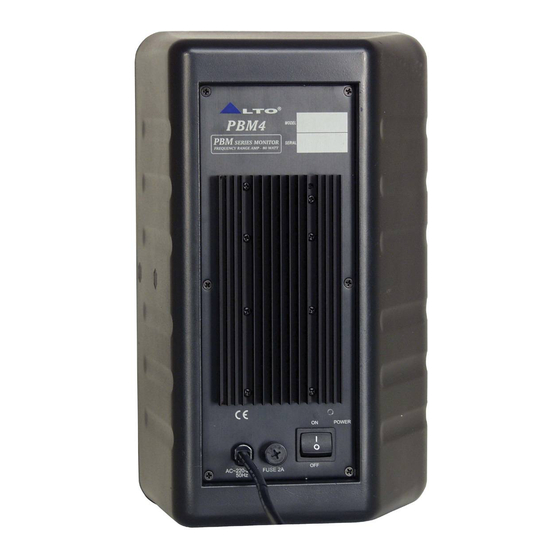
- Page 11 This switch is used to turn the main power ON/OFF. 25 AC INLET with FUSE 2A Use it to connect your PBM4 to the main AC with the supplied AC cord. Please check the voltage available in your country and how the voltage for your PBM4 is configured before attempting to connect your PBM4 to the main AC.
-
Page 12: Installation & Connection
Ok, you have got to this point and you are now in the position to successfully operate your PBM4. However , we advise you to read carefully the following section to be the real master of your own mix. Not paying attention enough to the input signal level, to the routing of the signal and the assignment of the signal will result in unwanted distortion, a corrupted signal or no sound at all. - Page 13 5. INSTALLATION AND CONNECTION Ring Return Signal Sleeve Ring Strain Clamp Tip Send Signal Sleeve Ground/Screen Use for Insert Points 1/4" Stereo (TRS) Jack Plug 2 Hot(+) 2 Hot(+) 1 Ground/Screen 1 Ground/Screen 3 Cold(-) 3 Cold(-) Use for Balanced Mic Inputs Use for Main output (For unbalanced use, leave pin3 unconnected) (For unbalanced use, connect pin 1 to 3)
-
Page 14: Preset List
6. PRESET LIST Controllable Parameter Preset Description Parameter Variable range Rev.decay time 360ms Simulate a small acoustic space of the sound. WARM HALL Pre delay 45ms Rev.decay time 290ms Simulate a large acoustic space of the sound. BRIGHT HALL Pre delay 23ms Rev.decay time 210ms... -
Page 15: Block Diagram
7. BLOCK DIAGRAM... -
Page 16: Technical Specifications
8. TECHNICAL SPECIFICATION Input channels Microphone Input Electronically balanced, discrete input configuration Frequency response 10 Hz to 55 kHz, +/ 3 dB 0.05% at +4 dBu, 1 kHz Distortion(THD&N) Gain 30 dB SNR(Signal to Noise Ratio) >94 dB Line input Electronically balanced Frequency response 10 Hz to 55 kHz, +/ 3 dB... -
Page 17: Warranty
8. WARRANTY 1. WARRANTY REGISTRATION CARD To obtain Warranty Service, the buyer should first fill out and return the enclosed Warranty Registration Card within 10 days of the Purchase Date. All the information presented in this Warranty Registration Card gives the manufacturer a better understanding of the sales status, so as to provide a more effective and efficient after-sales warranty service. - Page 18 NO. 1, Lane 17, Sec. 2, Han Shi West Road, Taichung 40151, Taiwan http://www.altoproaudio.com Tel: 886-4-22313737 email: alto@altoproaudio.com Fax: 886-4-22346757 All rights reserved to ALTO. All features and content might be changed without prior notice. Any photocopy, translation, or reproduction of part of this manual without written permission is forbidden. Copyright 2007 Seikaku Group NF02055-1.2...
Need help?
Do you have a question about the PBM4 and is the answer not in the manual?
Questions and answers