Table of Contents
Advertisement
Quick Links
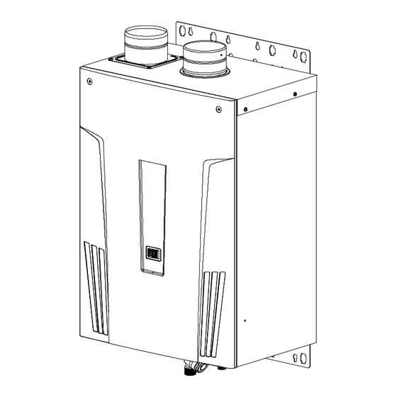
520
Direct Vent Indoor and Outdoor Models
On-Demand Condensing Water Heater
Installation Manual and Owner's Guide
Gas Tankless Water Heater
520 Direct Vent Indoor and
Outdoor Models
Suitable for potable water heating and space-heating *
*Please refer to local codes for space-heating compliance.
FEATURING
ENDLESS HOT WATER
ON DEMAND USAGE
COMPACT, SPACE SAVING
ENERGY CONSERVATION
COMPUTERIZED SAFETY
NO PILOT LIGHT
EASY-LINK SYSTEM
ANSI Z21.10.3 and CSA 4.3
WARNING
This product must be installed and
serviced by a licensed plumber, a
licensed gas fitter, or a professional
service
technician.
installation and/or operation, or
installation
by
person, will void the warranty.
WARNING
If the information in this manual is
not followed exactly, a fire or
explosion may result, causing
property damage, personal injury, or
death.
If you have any questions, please
call or write to:
500 Tennessee Waltz Parkway
Ashland City, TN 37015
Toll Free: 1- 877-737-2840
Improper
an
unqualified
Advertisement
Table of Contents

Subscribe to Our Youtube Channel
Related Manuals for American Water Heater 520


Summary of Contents for American Water Heater 520
- Page 1 WARNING Gas Tankless Water Heater 520 Direct Vent Indoor and If the information in this manual is not followed exactly, a fire or Outdoor Models explosion may result, causing Suitable for potable water heating and space-heating * property damage, personal injury, or death.
-
Page 2: Table Of Contents
Contents CONTENTS SPECIFICATIONS 520 Indoor and Outdoor Installation Manual Natural Gas Input Min: 13,000 Btu/h SPECIFICATIONS………………………………... INTRODUCTION……………………………….… (Operating Range) Max: 199,000 Btu/h SAFETY GUIDELINES…………….…………….. Propane Input Min: 13,000 Btu/h INSTALLATION………………………………..…. (Operating Range) Max: 199,000 Btu/h General………………………………………..… Gas Connection ¾” NPT Included Accessories…………………..…... -
Page 3: Introduction
The 520 Indoor and Outdoor are on-demand, tankless water heaters designed to efficiently supply endless hot water for your needs. The 520 Indoor and Outdoor are high efficiency models with an in-build secondary heat exchanger that absorbs latent heat from the exhaust gas. -
Page 4: Safety Guidelines
National Electrical Codes: ANSI/NFPA 70 in the USA or CSA standard C22.1 Canada Electrical Code Part 1 in Canada. Carefully plan where you intend to install your 520 Indoor and Outdoor Water Heater. Please ensure: Your water heater will have enough combustible air and proper ventilation. -
Page 5: Installation
For more information, refer to p. 20. The manufacturer does not recommend installing the 520 Indoor models in an attic due to safety issues. If you install your 520 Indoor models in an attic: Make sure your unit will have enough combustion air and proper ventilation. -
Page 6: General
Check that the installation manual, the communication cable, the product registration card and the PVC adaptor are included with the unit (the adaptor comes with the 520 Indoor model only). For details on how to connect the adaptor, refer to P.14. -
Page 7: Optional Items
2. Pipe cover: 9007606005 The Pipe cover protects the plumbing pipes to the 520 Indoor and Outdoor models from unexpected adjustments. This pipe cover is fixed to the bottom of the water heater, which hides the plumbing and improves the visual aspects of the whole installation for the water heater. -
Page 8: Warning For Installations
The area under an overhang must be open to opening, and with in 3 ft. in Canada of any air three sides. (520 Outdoor only) intake or building opening. (520 Outdoor only) (Refer to p.15) Do not install next to a dryer or any source of... -
Page 9: Outdoor Installation
1. Install the 520 Outdoor model only in areas with mild, temperate climates. 2. The 520 Outdoor model shall be wall-mounted or mounted on a stand. Locate the 520 Outdoor model in an open, unroofed area and maintain the following minimum clearances: Top 36”... -
Page 10: Venting Instructions
Installation 520 Indoor model INSTALLATION The 520 Indoor models are equipped with a thermistor and hi-limit switch for the exhaust gas, detecting excess temperatures within the flue and enabling the unit to safely stop operations if needed. These components are always monitoring exhaust gas conditions in order to prevent heat damage to PVC (Plastic) venting if PVC is used. - Page 11 Installation -Exhaust vent (PVC & ABS vent) - The 520 Indoor models can be connected with PVC or ABS venting (temperature rated up to 149°F). However, the manufacturer recommends PVC (or ABS) venting certified to ULC S636 standards. Item Material...
-
Page 12: Vent Termination
A proper sidewall direct-vent terminator is recommended when the water heater is vented through a sidewall. General rules for venting the 520 Indoor water heater are: Place the water heater as close as possible to the vent terminator. The vent collar of the water heater must be fastened directly to an unobstructed vent pipe or PVC adaptor. - Page 13 Connection between exhaust vent collar and PVC piping See the next page for instructions. How to install PVC venting with the 520 Indoor (For Exhaust) 1. Connect the PVC adaptor* directly on the exhaust vent collar of the water heater.
- Page 14 Exhaust vent collar of Exhaust vent collar of Intake vent collar the 520 Indoor (Female) the 520 Indoor (Female) Intake vent collar *PVC adaptor is included with the 520 Indoor. -Stainless steel Venting Illustrations- Vertical Installation Diagram Horizontal Installation Diagram Wall Rain Cap...
-
Page 15: Vent Clearances
Installation -Vent clearances- Canada U.S.A Direct vent and other than Direct Direct vent Other than Direct Vent Vent Clearance above grade, veranda, porch, deck, 1 foot 1 foot 1 foot or balcony. 4 feet from below or side Clearance to window or door that may be 3 feet 1 foot opening. -
Page 16: Additional Clearances
Installation -Additional clearances - Please follow all local and national codes in regards to proper termination clearances. In the absence of such codes, the following clearances can be used as guidelines. Local codes supersede these guidelines. For sidewall terminations 2ft. 3ft. -
Page 17: Gas Supply And Gas Pipe Sizing
Inlet gas pressure must not exceed the above maximum values; gas pressure above the specified range will cause dangerous operating conditions and damage to the unit. Until testing of the main gas line supply pressure is completed, ensure the gas line to the 520 is disconnected to avoid any damage to the water heater. - Page 18 Size the gas pipe appropriately to supply the necessary volume of gas required for the 520 Indoor and Outdoor models (199,000 BTU/h for both Natural Gas and Liquid Propane) using ANSI233.1/NFPA 54 in the USA or CAN/CSA B149.1 in Canada or local codes.
-
Page 19: Water Connections
Condensate drain port Do not reverse the hot Water outlet outlet and cold inlet (HOT) connections to the 520 Water Heater. This will not GAS inlet CAUTION properly active the water heater. -
Page 20: Pressure Relief Valve
Installation PRESSURE RELIEF VALVE The 520 has a high-temperature shut off switch built in as a standard safety feature (called a Hi-Limit switch) therefore a “pressure only” relief valve is required. This unit does not come with an approved pressure relief valve. - Page 21 Discharge condensate (acidic water) in accordance with all local codes and common safety practices. WARNING The 520 models are high efficiency condensing water heaters that produce condensate (acidic water). The acidic condensate generated in the secondary heat exchanger can be neutralized by the Neutralizer accessory.
- Page 22 All portions of the condensate drain (neutralizer and drain tube) must be at a lower WARNING elevation than the 520 to prevent condensate water from building up inside the heat exchanger. Condensate cannot be effectively neutralized if the neutralizer elements inside the Neutralizer accessory have been completely consumed.
-
Page 23: Electrical Connections
Verify proper CAUTION operation after servicing. The 520 must be electrically grounded. Do not attach the ground wire to either the gas or the water piping. The 520 requires 120 VAC / 60 Hz electrical power supply that is properly grounded. -
Page 24: Remote Controller Connection
Minimum 18AWG wire (No polarity) Maximum 400 feet long *For detailed connection instructions to the remote controller accessory, refer to the remote controller’s Installation Manual. Remote controller terminal of the 520 Back of remote Front of remote Connect other end to these terminals Connect to these terminals │... -
Page 25: Pump Control Connection
To control a recirculation pump, connect the pump to the “Pump connector” in the 520 as shown in the diagram below. (In an Easy-Link system, connect the pump ONLY to the “PARENT” unit.) The pump is to be connected using suitable relays shown in the diagram below. -
Page 26: Pump Control Mode
After set temperature has been reached in the storage tank, the 520 will fire off and limit the water flow rate to less than 2.6 GPM, to continually monitor the temperature throughout the system. - Page 27 Installation D) Normal Control (Default setting): No.5 and No.6 OFF Feature: This mode provides no special pump control. Pump activation can only be turned ON or OFF by the remote controller. Function: The pump will run continually all the time as long as there is a power supply to the water heater.
-
Page 28: Easy-Link System
Locate the two banks of dipswitches to the left of the 3-digit 7-seg. LED on the computer board of the 520 that you select to be the “PARENT” unit. Change dipswitch No. 10 on the right bank of dipswitches to the ON position. Do not change any dipswitches on any of the “CHILD” units. -
Page 29: Computer Board
7. Make sure the “3-digit 7-seg. LED” of all the units’ computer boards display the unit #. The numbering system of the 520 automatically allocates the unit # to each water heater in the Easy- Link system, in accordance with the table below. - Page 30 Installation (C) Examples of incorrect settings and/or connections CASE 1: Unless you change dipswitch No.10 of the “PARENT” unit to the “ON” position, the system will not work as an Easy-Link system. The units will operate as individual units. PARENT unit CHILD-1 unit C o n n e c t o r s C o n n e c t o r s...
- Page 31 Installation CASE 3: If you connect the “PARENT connector” of the “CHILD-1” unit to the “[1] connector” of the “CHILD-2” unit, the “CHILD-2” unit will operate as an individual unit, and will not be part of the Easy-Link system. Wrong connection between the “CHILD-1” unit and the “CHILD-2” unit CHILD-1 unit PARENT unit CHILD-2 unit...
-
Page 32: Applications
The 520 can be used to supply potable water and space heating and shall not be connected to any heating system or component(s) previously used with non-potable water where any chemicals were added to the water heating appliances. -
Page 33: Dual-Purpose Hot Water Heating
Applications -Dual-purpose hot water heating- (Domestic and Space Heating): Diagramatic Layout of Radiant Heating and Domestic Water Heater Per Mass. Code An approved Pressure Only Relied An approved Pressure Only Valve, Tie to Location approved By Relief Valve, Tie to Location Cold Inlet approved by Local Codes and Local Codes and Must Meet BTU... -
Page 34: Initial Operation
Initial Operation INITIAL OPERATION FOR YOUR SAFETY, READ BEFORE OPERATING Check the GAS and WATER CONNECTIONS for leaks before firing unit for the first time. Open the main gas supply valve to the unit using only your hand to avoid any spark. Never use tools. -
Page 35: Operating Safety
Operating Safety ’ ’ ’ OPERATING SAFETY FOR YOUR SAFETY READ BEFORE OPERATING WARNING: If you do not follow these instructions exactly, a fire or explosion may result causing property damage, personal injury or loss of life. A. This water heater does not have a pilot. It is equipped with an ignition device that automatically lights the burner. - Page 36 Operating Safety DANGER Vapors from flammable liquids will explode and catch fire causing death or severe burns. Do not use or store flammable products such as gasoline, solvents or adhesives in the same room or area near the water heater. Keep flammable products: Vapors: 1.
-
Page 37: Normal Operation
TEMPERATURE SETTINGS -ON THE 520- On the 520, changing the temperature setting can be done simply by using the 3-digit 7-seg. LED, and the “Increase” & “Decrease” buttons on the computer board (remote controller is not required) The 520 will display the set temperature on the 3-digit 7-Seg. LED on the computer board. - Page 38 Set temperature (Example 110°F) 3. Scroll to the desired set temperature. DO NOT set to 185 °F if you use your 520 water heater in a recirculation system. This will cause damage to the heater and void the warranty. │...
-
Page 39: Indoor Installation
In any areas subject to freezing temperatures, the manufacturer highly recommends an indoor installation with the 520 Indoor model. In such an installation, freezing issues can only occur if cold air enters through the venting into the heat exchanger, whether by negative pressures within the installation location or by strong outside winds. -
Page 40: Maintenance And Service
Normal Operation MAINTENANCE AND SERVICE Turn off the electrical power supply and close the manual gas control valve and the manual water control valve before servicing. WARNING Clean the cold-water inlet filter. (Refer to diagram below) Be sure that all openings for combustion and ventilation air are not blocked. Check that the exhaust vent pipe is not blocked. -
Page 41: Troubleshooting
Troubleshooting TROUBLESHOOTING GENERAL PROBLEM SOLUTIONS It takes long time to get The time it takes to deliver hot water from the water heater to hot water at the your fixtures depends on the length of piping between the two. fixtures. The longer the distance or the bigger the pipes, the longer it will take to get hot water. - Page 42 Troubleshooting PROBLEM SOLUTIONS Unit does not ignite when Is the flow rate over 0.5 GPM? (p. 37) water goes through the unit. Check for the filter on cold water inlet. (p. 40) Check for reverse connection and cross connection. If you use the remote controller, is the power button turned on? The fan motor is still spinning This is normal.
-
Page 43: Error Codes
Troubleshooting ERROR CODES The 520 units are self diagnostic for safety and convenience when trouble shooting. If there is a problem with the installation or the unit, it will display a numerical error code on the 3- digit 7-Seg. LED on the computer board (visible through a window on the front cover) or remote controller (if installed) to communicate the source of the problem. - Page 44 -FAULT ANALYSIS OF ERROR CODES- If there is a problem with the installation of the 520, it will display a numerical error code on the 7-seg LED of the computer board or the remote controller (if installed) to communicate the source of the problem.
-
Page 45: Components Diagram
Components Diagram COMPONENTS DIAGRAM Case assembly Other than the case assembly (No.15) and front cover (No.16), all of the 520 Outdoor parts are the same as the 520 Indoor. The 520 Outdoor doesn’t have fan motor for exhaust (No.124). 520 Indoor... -
Page 46: Exhaust Thermistor
4 2 3 7 1 1 1 1 4 7 1 0 7 2 0 Burner assembly The 520 Indoor and Outdoor share the same components. 10 1 1 0 2 1 03 1 5 2 1 5 2 1 0 4... -
Page 47: Water Way Assembly
Components Diagram Water way assembly Other than Part# 456, Part# 459, Part# 460 and Part# 461, the 520 Indoor and the Outdoor share the same components. The 520 Outdoor doesn’t have hi-limit switch for exhaust (No.442) and exhaust thermistor assembly (No.706). -
Page 48: Parts List
Parts List PARTS LIST Item# Part# Description Item# Part# Description 319143-009 Case assembly for 520 Indoor Manifold assembly with 319143-046 gas valve assembly LP Front cover for 520 Indoor 319143-010 Intake air port assembly 319143-011 Manifold assembly with 319143-047 gas valve assembly NA... - Page 49 Heater fixing plate 20 319143-089 319143-124 Pan screw M4×6 (W/Washer) Heater fixing plate 16 319143-090 319143-125 319143-091 O-ring P15 FKM 319143-126 520 Indoor & Outdoor PCB Flow sensor Transformer 319143-092 319143-127 Hot pipe Junction box inner plate 319143-093 319143-128 Joint elbow...
-
Page 50: Output Temperature Chart
Output Temperature Chart OUTPUT TEMPERATURE CHART Output Temperature vs. GPM (Max. 9.0 GPM) with Various Ground Water Temperature Chart is based on properly sized gas line 10.0 40 F 50 F 60 F 70 F Out put Hot Water Temperature 40 F 50 F 60 F... -
Page 51: Limited Warranty
DAMAGES, LOSS OF USE, OR INCONVENIENCE. SOME STATES DO NOT ALLOW THE EXCLUSION OR LIMITATION OF INCIDENTAL OR CONSEQUENTIAL DAMAGES, SO THE ABOVE LIMITATION MAY NOT APPLY TO YOU. 2. Warranty for models: 520 Indoor and Outdoor [Unit: Year] Application... - Page 52 Warranty 3. Repair, Replacement or Refund: The manufacturer or its authorized Service Representative will, at its sole discretion, repair or replace any failed or defective mechanical or electrical parts, or components thereof, or, if the manufacturer or its authorized Service Representative cannot replace said parts, and repair is not commercially practicable, the manufacturer or its authorized Service Representative will refund the purchase price.
Need help?
Do you have a question about the 520 and is the answer not in the manual?
Questions and answers