Table of Contents
Advertisement
Quick Links
Instruction Manual
COMMERCIAL ELECTRIC WATER HEATER
52/80/120 SERIES 100
Tennessee Waltz Parkway
INSTALLATION - OPERATION - SERVICE
Ashland City, TN 37015
MAINTENANCE - LIMITED WARRANTY
(OPTIONAL)
Thank you for buying this energy efficient water heater. We
appreciate your confidence in our products.
PLACE THESE INSTRUCTIONS ADJACENT TO HEATER AND NOTIFY OWNER TO KEEP FOR FUTURE REFERENCE.
PRINTED 0917
100293647 2000548787 (Rev. A)
1
Advertisement
Table of Contents

Subscribe to Our Youtube Channel
Related Manuals for American Water Heater 52 Series


Summary of Contents for American Water Heater 52 Series
- Page 1 Instruction Manual COMMERCIAL ELECTRIC WATER HEATER 52/80/120 SERIES 100 Tennessee Waltz Parkway INSTALLATION - OPERATION - SERVICE Ashland City, TN 37015 MAINTENANCE - LIMITED WARRANTY (OPTIONAL) Thank you for buying this energy efficient water heater. We appreciate your confidence in our products. PLACE THESE INSTRUCTIONS ADJACENT TO HEATER AND NOTIFY OWNER TO KEEP FOR FUTURE REFERENCE.
-
Page 2: Safe Installation, Use, And Service
SAFE INSTALLATION, USE, AND SERVICE The proper installation, use and servicing of this water heater is extremely important to your safety and the safety of others. Many safety-related messages and instructions have been provided in this manual and on your own water heater to warn you and others of a potential injury hazard. -
Page 3: General Safety Information
GENERAL SAFETY INFORMATION PRECAUTIONS HYDROGEN GAS (FLAMMABLE) DO NOT USE THIS WATER HEATER IF ANY PART HAS BEEN EXPOSED TO FLOODING OR WATER DAMAGE. Immediately call a qualified service technician to inspect the water heater and to replace any part of the control system which has been under water. -
Page 4: Table Of Contents
TABLE OF CONTENTS SAFE INSTALLATION, USE, AND SERVICE ......2 TEMPERATURE REGULATION ........21 HIGH TEMPERATURE LIMIT CONTROLS (ECO) ..21 GENERAL SAFETY INFORMATION ........3 THERMOSTAT CONTROLS .........21 Precautions ..............3 THERMOSTAT SETTINGS - SURFACE MOUNT Hydrogen Gas (Flammable) ..........3 CONTROL ..............21 INTRODUCTION ..............5 ELECTRONIC CONTROL MODELS OPERATION ...22 Preparing for the Installation ...........5 Control System Features ..........22... -
Page 5: Introduction
INTRODUCTION Thank You for purchasing this water heater. Properly installed The principal components of the heater are identified on pages and maintained, it should give you years of trouble free service. 7 & 8. The model and rating plate on page 6 interprets certain markings into useful information. -
Page 6: Dimensions And Capacities
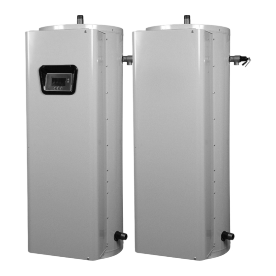
DIMENSIONS AND CAPACITIES This Instruction Manual covers two models of commercial electric water heaters: 3/4” NPT These two models are equipped from the factory with OPENING different controls. In this Instruction Manual ,one model is factory equipped with a surface mounted thermostat/ECO combination control and is referred to as the “Surface Mount Control”... -
Page 7: Approvals
APPROVALS Low Lead Content All models meet National All models are listed by Sanitation Foundation Underwriters Laboratories NSF-5 requirements. Inc. MODEL AND RATING COMMERCIAL STORAGE TANK WATER HEATER LISTED 22U1 Low Lead Content MODEL NUMBER SERIAL NUMBER ITEM ID / PART NUMBER WATTS WATTS No. -
Page 8: Features And Components
FEATURES AND COMPONENTS Figure 3. Electronic Control Models... - Page 9 FEATURES AND COMPONENTS Figure 4. Surface Mount Control Models...
-
Page 10: Locating The New Water Heater
LOCATING THE NEW WATER HEATER FACTS TO CONSIDER ABOUT THE LOCATION • Near a floor drain. The heater should be located in an area where leakage of the tank or connections will not result in damage to the area adjacent to the heater or to lower floors CAUTION of the structure. -
Page 11: Installation
INSTALLATION REQUIRED ABILITY CONTAMINATED WATER Installation and service of this water heater requires ability This water heater shall not be connected to any heating equivalent to that of a qualified agency (page 2) in the field system(s) or component(s) used with a non-potable water involved. -
Page 12: Water Line Connections
If replaced, the new valve must meet the requirements of local codes, but not less than a combination temperature and pressure relief valve rated/sized and certified as indicated in the above paragraph. The new valve must be marked with a maximum set pressure not to exceed the marked hydrostatic working pressure of the water heater (150 psi = 1,035 kPa) and a discharge capacity not less than the water heater Btu/hr or KW input rate... -
Page 13: Electrical
ELECTRICAL GENERAL An electrical ground is required to reduce risk of electrical shock or possible electrocution. The water heater should be connected The installation must conform with these instructions and the to a separate grounded branch circuit with over-current protection local code authority having jurisdiction and the requirements of and disconnect switch. -
Page 14: Amperage Table/Over-Current Protection
Table 4. Required Electrical Characteristics Full Load Current In Amperes Single Phase Three Phase Number Of Element Number Of Ther- Number Of KW Input Elements wattage 208V 240V 277V 480V 208V 240V 480V mostats Fuses 4000 13.5 4500 5000 6000 - - - - - - 3000... -
Page 15: Wiring Diagrams
WIRING DIAGRAMS Figure 8. CCB (Central Control Board) Control Circuit Diagram - Electronic Control Models... -
Page 16: Power Circuit Diagrams - Electronic Control Models
WIRING DIAGRAMS POWER CIRCUIT DIAGRAMS - ELECTRONIC CONTROL MODELS The water heater’s electrical components are pictured and identified on page 7. The following describes the heater circuits and includes wiring diagrams. All heater circuits are designed for 60/50 hertz alternating current. The water heater circuit wiring is 12 AWG, AWM, or TEW type, rated 600 volts, 105°C. - Page 17 WIRING DIAGRAMS Figure 10. Nine-Element Single- and Three-Phase Power Circuits CONVERSION TO SINGLE PHASE CONVERSION TO THREE PHASE When the heater is shipped for connection to a three-phase When heater is shipped for connection to a single-phase electrical electrical service, it may be connected to a single-phase electrical service, it may be connected to a three-phase electrical service service of the same voltage by: of the same voltage by:...
-
Page 18: Power Circuit Diagrams - Surface Mount Control Models
WIRING DIAGRAMS POWER CIRCUIT DIAGRAMS - SURFACE MOUNT CONTROL MODELS The water heater’s electrical components are pictured and identified on page 8. The following describes the heater circuits and includes wiring diagrams. All heater circuits are designed for 60/50 hertz alternating current. The water heater circuit wiring is 12 AWG, AWM, or TEW type, rated 600 volts, 105°C. - Page 19 WIRING DIAGRAMS Figure 12. Nine Elements - Single And Three Phase CONVERSION TO SINGLE PHASE CONVERSION TO THREE PHASE When the heater is shipped for connection to a three-phase When heater is shipped for connection to a single-phase electrical service, it may be connected to a single-phase electrical electrical service, it may be connected to a three-phase electrical service of the same voltage by: service of the same voltage by:...
-
Page 20: Operation
OPERATION GENERAL 3. Depress the red manual reset button on each Thermostat/ ECO combination control (Surface Mount Control Models only). Refer to the Features and Components section of this manual 4. Turn on the electrical disconnect switch. (pages 7 & 8) for the location of components mentioned in the instructions that follow. -
Page 21: Temperature Regulation
TEMPERATURE REGULATION THERMOSTAT SETTINGS - SURFACE MOUNT CONTROL HIGH TEMPERATURE LIMIT CONTROLS (ECO) Both the ELECTRONIC CONTROL and SURFACE MOUNT CONTROL model water heaters are equipped with one or more ECO (energy cut out) non adjustable high temperature limit control(s). An ECO is a normally closed switch that opens (activates) on a rise in temperature. -
Page 22: Electronic Control Models Operation
The control system senses temperature from a factory installed Table 5. Time to Burn Relationship for Normal Adult Skin Immersion Temperature Probe (see Figure 3). The “Operating Set Point” is adjusted to control water temperature. This is an Time for Permanent Water Time for 1st Degree Burn adjustable user setting in the control system’s “Temperatures... - Page 23 Help: The right Operational Button is pressed to access instructions and explanations for user settings, Operating States, Status Icons, manufacturer’s web address, technical support phone number and service agent contact information. Day/Time/Operating Mode: The current time and day are also displayed on the Desktop Screen.
-
Page 24: Temperatures Menu
Table 7. Operating States State Description The water heater is not in an active heating cycle. This usually indicates the temperature in the tank has Standby reached the Operating Set Point and the control system has terminated the heating cycle. The control system is in the Heating Mode. -
Page 25: Temperature Settings
DIFFERENTIAL SETTINGS TANK TEMPERATURE Adjustable user setting(s) 1°F to 20° range; factory default is 2°F. Non adjustable information display. Current water temperature as The water heaters covered in this Instruction Manual will have 3, sensed by the control system from the immersion Temperature 6 or 9 heating elements. -
Page 26: Heater Status Menu
HEATER STATUS MENU ALARM CONDITION Displays the status of the user definable Alarm Output function - This menu displays non adjustable operational information. see Alarm Output Setup Menu. Yes = alarm condition has been This menu contains more information that can be displayed on met, No = alarm condition has not been met. -
Page 27: Economy Mode Settings
Normal Operation Between: When this operating mode is Seven daily sub menus are listed at the bottom of the Economy active there will also be start and stop times to program. The Mode Setup menu. There are 3 Operating Modes in each sub normal Operating Set Point is used between the programmed menu;... - Page 28 Table 11. Economy Mode Settings: Time Clock Settings ACTION DISPLAY From the Desktop Screen navigate to the Economy Mode Setup menu. Use the Up/Down buttons to select (highlight in black) Current Time sub menu. Press the Operational Button underneath “CHANGE” to enter the Current Time sub menu.
- Page 29 Table 12. Economy Mode Set Up: Daily Operating Mode Settings ACTION DISPLAY Economy Mode All Day: From the Economy Mode Setup menu use the Up/Down buttons to select (highlight in black) the Daily sub menu for “Sun.” Press the Operational Button underneath “CHANGE”...
-
Page 30: Alarm Output Setup Menu
ALARM OUTPUT SETUP MENU DISPLAY SETTINGS MENU Permits user to set the condition (from a list of options) for when Permits user to set display options for viewing information on the UIM’s LCD screen. the CCB’s integral alarm output relay will be energized. Alarm relay connections (common, normally open, normally closed) are located on the J3 terminal strip on the CCB. -
Page 31: Current Fault / Alert Menu
Elapsed Time: Total accumulated time the control system (water message. The Fault/Alert message screen displays a brief heater) has been energized. description of the condition, contact information and access to the Advanced service information sub menu. Total Heating Time: Total accumulated time the control system has been in the heating mode. -
Page 32: Restore Factory Defaults Menu
RESTORE FACTORY DEFAULTS MENU This control system menu allows the user to restore most of the control system’s user settings to their factory default settings. User settings in the Alarm Output Setup and Display Settings menus are unaffected by executing Restore Factory Defaults. Table 13. -
Page 33: Anode Rod Inspection
ANODE ROD INSPECTION FLUSHING THE WATER HEATER Each water heater contains at least one anode rod, which will 1. Turn off the electrical supply to the water heater at the breaker slowly deplete (due to electrolysis) prolonging the life of the or disconnect switch. - Page 34 THE PROCESS FOR LIME SCALE REMOVAL IS AS FOLLOWS: OTHER SCALE REMOVAL: 1. Turn off electrical disconnect switch. 1. Flush cleaned ends of elements with water when deliming or cleaning is completed. 2. Drain the heater following DRAINING instructions. 2. Remove sediment and scale from the tank bottom through 3.
-
Page 35: Troubleshooting Checklist
TROUBLESHOOTING CHECKLIST CHECKLIST ABNORMAL SOUNDS Before calling for service, check the following points to see if the 1. Sediment or lime scale accumulations on the elements causes cause of trouble can be identified and corrected. sizzling and hissing noises when the heater is operating. •... -
Page 36: Leakage Checkpoints
LEAKAGE CHECKPOINTS INSTRUCTIONS: USE THIS ILLUSTRATION AS A GUIDE WHEN CHECKING FOR SOURCES OF WATER LEAKAGE. Where possible, remove or lift top cover to examine threads of ttings installed into tank for evidence of leakage. Correct tting leaks as necessary. Relief valve operation and leakage may be due to water expansion during heating cycle or foreign material on seat of valve. -
Page 37: Piping Diagrams
PIPING DIAGRAMS... - Page 38 PIPING DIAGRAMS...
- Page 39 PIPING DIAGRAMS...
- Page 40 PIPING DIAGRAMS...
-
Page 41: Piping Diagrams
PIPING DIAGRAMS... - Page 42 PIPING DIAGRAMS...
- Page 43 PIPING DIAGRAMS...
- Page 44 PIPING DIAGRAMS...
- Page 45 PIPING DIAGRAMS...
- Page 46 PIPING DIAGRAMS...
-
Page 47: Piping Diagrams
PIPING DIAGRAMS... - Page 48 PIPING DIAGRAMS...
-
Page 49: Manifold Kits
MANIFOLD KITS ALL DIMENSIONS IN INCHES Table 14. Manifold Kits with Two Heaters Tank Capacity Part MANIFOLD KITS (Gallons) Number 100109231 66 1/4 56 3/4 27 1/4 13 1/4 100109231 70 1/2 60 1/4 31 1/4 9 3/4 100109231 73 1/4 64 1/2 35 3/4 5 1/2... -
Page 50: Notes
NOTES... -
Page 51: Notes
NOTES... - Page 52 www.hotwater.com Copyright © 2017 A. O. Smith Corporation, All rights reserved.
Need help?
Do you have a question about the 52 Series and is the answer not in the manual?
Questions and answers