Table of Contents
Advertisement
Advertisement
Table of Contents

Related Manuals for Motorola RMU2080d


Summary of Contents for Motorola RMU2080d
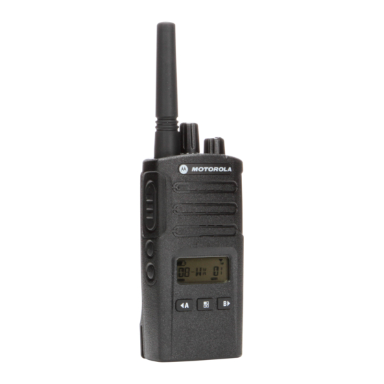
- Page 1 Two-Way Radios User Guide RMU2080d Display model...
- Page 2 Open Source Software Legal Notices: This Motorola product contains Open Source Software. For information regarding licenses, acknowledgements, required copyright notices and other usage terms, refer to the documentation for this Motorola product at: http://businessonline.motorolasolutions.com Go to: Resource Center > Product Information > Manual > Accessories.
-
Page 3: Table Of Contents
Battery Features..... . 15 CONTENTS About the Li-Ion Battery ... . . 15 Battery Recycling and Disposal . - Page 4 Signal Strength Indicator and Programming Scramble ....39 Channel Busy Indicators ...30 Programming Maximum Number Talk Range ......30 Of Channels.
- Page 5 RM UHF Frequencies Chart ... . .62 RMU2080d – UHF Default Frequencies Chart ......65 CTCSS and PL/DPL Codes .
-
Page 6: Product Safety
For a list of Motorola-approved antennas, PRODUCT SAFETY batteries and other accessories, visit the following website which lists approved PRODUCT SAFETY AND RF accessories: EXPOSURE COMPLIANCE www.motorolasolutions.com/RMseries Before using this product, read the operating instructions and RF energy awareness information... -
Page 7: Introduction
Thank you for purchasing the Motorola® RM 8000 West Sunrise Boulevard Series™ Radio. This radio is a product of Plantation, Florida 33322 Motorola's 80 plus years of experience as a world leader in the designing and PACKAGE CONTENTS manufacturing of communications equipment. - Page 8 For a copy of a large-print version of this user guide or for product-related questions, contact 1-800-448-6686 in the USA 1-800-461-4575 in Canada 1-888-390-6456 on TTY (Text Telephone) For product related information, visit us at: www.motorolasolutions.com/RMseries English...
-
Page 9: Fcc Licensing Information
To transmit on these frequencies, you are FCC LICENSING required to have a license issued by the FCC. INFORMATION Application is made available on FCC Form 601 and Schedules D, H, and Remittance Form INTERFERENCE INFORMATION 159. This device complies with Part 15 of the FCC Rules. - Page 10 Changes or modifications not expressly approved by Motorola may void the user’s authority granted by the FCC to operate this radio and should not be made. To comply with...
-
Page 11: Batteries And Chargers Safety
Use of accessories not recommended by To reduce risk of electric shock, unplug the Motorola may result in risk of fire, electric charger from the AC outlet before attempting shock, or injury. -
Page 12: Operational Safety Guidelines
OPERATIONAL SAFETY located at the bottom of the charger. GUIDELINES • Make sure that the cord is located where it will not be stepped on, tripped over, or subjected to • Turn the radio OFF when charging battery. water, damage, or stress. •... -
Page 13: Radio Overview
On/Off/Volume Knob Audio Accessory Microphone 2 Pin Connector Indicator PTT (Push-To- Talk) Button SB1 - Monitor Button Battery SB2 - Scan/ Nuisance Channel Display Delete Model Label Left Navigation Arrow/Programmable Menu Button A RMU2080d Right Navigation Arrow/Programmable Button B English... -
Page 14: On/Off/Volume Knob
It also allows you to move through all the features while in Programming Mode. Antenna Default set to preset Channel 1. For model RMU2080d, the antenna is non-removable. • Programmable Button LED Indicator Allows you to choose level or toggle options for features the Menu is on. -
Page 15: Side Buttons
Side Buttons • Programmable Button Push-to-Talk (PTT) Button Allows you to choose level or toggle options for • Press and hold down this button to talk, release it features the Menu is on. to listen. Default set to Backlight Mode. Side Button 1 (SB1) Note: A short press of either Programmable... - Page 16 This User Guide covers the RMU2080d model from the RM Series radios. The radio’s model is shown on the bottom of the radio and provides the following information: Table 1: RMU2080d Radio Specifications Transmit Number of Frequency Model Power Antenna...
-
Page 17: Battery Features
Motorola batteries are designed specifically to the battery life. be used with a Motorola charger and vice About the Li-Ion Battery versa. Charging in non-Motorola equipment may lead to battery damage and void the The RM Series radio comes equipped with a battery warranty. -
Page 18: Battery Recycling And Disposal
1-800-8-BATTERY specific requirements and information in your This internet site and telephone number also area. Motorola fully endorses and encourages provides other useful information concerning the recycling of Li-Ion batteries. In the U.S. and recycling options for consumers, businesses Canada, Motorola participates in the and governmental agencies. -
Page 19: Installing The Lithium-Ion (Li-Ion) Battery
Slots Turn OFF the radio. Turn OFF the radio. With the Motorola logo side up on the battery Push down the battery latch and hold it while pack, fit the tabs at the bottom of the battery removing the battery. -
Page 20: Holster
Holster Power Supply, Adaptor and Drop-in Tray Charger Drop-in Tray Charger Power Supply The radio is equipped with one Drop-in Tray Charger and one Power Supply with Adaptor. For more information, refer to “Chargers” on Insert the radio into the base of the holster at an page 76. -
Page 21: Battery Life Information
Battery Life Information When the Battery Save feature is set to ON (enabled by default), the battery life lasts longer. The following table summarizes battery life estimations: Table 2: Li-Ion Battery Life with Tx Power 2 Watts Battery Type Battery Save OFF Battery Save ON Standard 12 Hours... -
Page 22: Battery Meter
Battery Meter The battery meter located in the upper left corner of the radio display indicates how much battery power the radio has remaining. Table 3: RM Series Battery Meter Battery Meter Battery Type 3 Bars 2 Bars 1 Bar Li-Ion 35 –... -
Page 23: Charging The Battery
Note: The radio comes with a Standard Power Supply. To charge the battery (with the radio attached), place it in a Motorola-approved Drop-in Tray Single Unit Charger or Drop-in Tray Multi Unit Charger. Drop-in Tray SUC Place the Drop-in Tray Charger on a flat surface. - Page 24 OFF to ensure a full alignment ribs in the Drop-in Tray Single Unit charge. See “Operational Safety Guidelines” Charger. on page 10 for more information. Table 4: Motorola Authorized Batteries Charging A Stand-Alone Battery Part Number Description PMNN4434_R...
-
Page 25: Drop-In Tray Charger Led Indicators
Drop-in Tray Charger LED Indicators Table 5: Charger LED Indicator Status LED Indicator Comments Green for approximately 1 second Power On Steady Red Charging Steady Green Charging Complete Red Fast Flash Battery Fault (*) Amber Slow Flash Waiting to Charge (**) Battery empty Flash Red 1 Time Battery low... -
Page 26: Estimated Charging Time
If there is NO LED indication: Check if the radio with battery, or the battery alone, is inserted correctly. (refer to step 4 of "Charging with the Drop-in Tray Single Unit Charger (SUC)" on page 21) Ensure that the power supply cable is securely plugged into the charger socket using an appropriate AC outlet and there is power to the outlet. - Page 27 Charging a Radio and Battery using Place the Multi-Unit Charger on a flat surface. a Multi Unit-Charger - MUC (Optional Insert the power cord plug into the MUC’s dual Accessory) pin connector at the bottom of the MUC. Plug the power cord into an AC outlet. Turn the radio OFF.
-
Page 28: Multi-Unit Charger Led Indicators
Multi-Unit Charger LED Indicators Table 7: Charger LED Indicator Status LED Indicator Comments Green for approximately 1 second Power On Steady Red Charging Steady Green Charging Complete Red Fast Flash Battery Fault (*) Amber Slow Flash Waiting to Charge (**) Battery empty Flash Red 1 Time Battery low... - Page 29 If there is NO LED indication: Check if the radio with battery or the battery alone, is inserted correctly (refer to step 5 of "Charging a Radio and Battery using a Multi Unit-Charger - MUC (Optional Accessory)" on page 25). Make sure the power cord is securely plugged into the MUC and the appropriate AC outlet.
-
Page 30: Getting Started
Note: Do not hold the radio too close to the ear GETTING STARTED when the volume is high or when adjusting the volume For the following explanations, refer to “Parts Of The Radio” on page 11. READING THE DISPLAY Keypad TURNING RADIO ON/OFF Hi Power Lock... -
Page 31: Selecting A Channel
SELECTING A CHANNEL Notes: To select a channel, turn the Channel Selector • To listen to all activity on a current channel, short Knob until you reach the desired channel. An press the SB1 to set the CTCSS/DPL code to 0. audible voice indicates the selected channel. -
Page 32: Signal Strength Indicator And Channel Busy Indicators
Signal Strength Indicator and Channel Busy TALK RANGE Indicators TALK RANGE When there is activity on a frequency, the radio Industrial Multi-Level displays the Signal Strength Indicator icon and the radio LED blinks faster. When your Model Inside steel/ Inside multi- radio is receiving (Rx) and there is activity on concrete Industrial level buildings... - Page 33 To establish a proper two-way communication, Scramble Code: Codes that make the the channel, frequency, and interference transmissions sound garbled to anyone eliminator codes must be the same on both listening who is not set to that specific code. radios. This depends on the stored profile that Bandwidth: Some frequencies have selectable has been preprogrammed on the radio: channel spacing, which must match other...
-
Page 34: Radio Led Indicators
RADIO LED INDICATORS RADIO STATUS LED INDICATION Channel Busy Solid Orange Cloning Mode Double Orange Heartbeats Cloning In Progress Solid Orange One Green Blink, One Orange Blink, One Green Blink, then repeat for 4 Fatal Error at Power up seconds Low Battery Orange Heartbeat Low Battery Shutdown... -
Page 35: Hands-Free Use/Vox
Accessory Port/ VOX can be temporarily disabled by pressing Connector the PTT button or by removing the audio Motorola RM Series radios can operate accessory. hands-free (VOX) when used with compatible VOX can also be activated using the VOX accessories. -
Page 36: Hands Free Without Accessories
Hands Free without Accessories (iVOX) hear the pre-programmed power up tone. 3 different power-up tones are available: • Press the PTT button while turning ON the radio • Power up tone and channel number blinks. to enable iVOX. The icon announcement, or •... -
Page 37: Keypad Lock/Unlock
Keypad Lock/Unlock MENU OPTIONS To access the radio MENU, short press the You can lock the keypad to avoid accidentally (Menu) button. The radio displays the changing your radio settings. To lock the radio feature options. For each options, use the keypad, press and hold the (Menu) button buttons to navigate. - Page 38 Accessories (iVOX)” on page 34 for more • 1 = Low sensitivity information). Once VOX/iVOX is enabled, short • 2 = Medium sensitivity press the (Menu) button. • 3 = High sensitivity If iVOX is enabled when you press the Once you have selected the desired sensitivity (Menu) button, the radio displays the following: level, you can:...
-
Page 39: Programming Features
When the radio is set to Advanced PROGRAMMING Configuration Mode, the icon displays FEATURES and the current channel aliasing name blinks to indicate that you can rotate the Channel ADVANCED CONFIGURATION MODE Selector Knob to select the channel you want Advanced Configuration mode is a special to program. -
Page 40: Programming Rx (Reception)
(Menu) button to scroll through the options until • To move along the different Programming Selection Mode without saving changes, short you reach ‘Frequency Programming Mode’. The radio display shows the frequency code as press the PTT Button or (Menu) Button. follows: •... -
Page 41: Programming Scramble
The radio display shows the CTCSS/DPL code Once you have entered Advanced as follows: Configuration Mode and selected the channel in which you want to enable Scramble ( scroll up or down through the programming modes by short pressing the PTT button or (Menu) button until the radio reaches the Scramble Programming Mode. -
Page 42: Programming Maximum Number
maximum number of channels. Long press the the CPS. Scramble is disabled when the value is set to ‘0’. PTT button to exit and save, or short press the PTT button to move to the next programming PROGRAMMING MAXIMUM NUMBER OF feature without saving. -
Page 43: Programming Microphone Gain Level
Tones’ selection by short pressing the PTT via the CPS. Call Tones is disabled when the value is set to ‘0’. button or (Menu) button. The radio display shows the Programming Call PROGRAMMING MICROPHONE GAIN Tone’ as follows: LEVEL To configure the Microphone Gain Level, enter the Advanced Configuration Mode and scroll up or down through the programming modes by short pressing the PTT button or... -
Page 44: Programming Microphone Accessory
medium gain or 3 = high gain) by pressing the buttons. Once you have selected the desired Microphone Gain Level, long press the PTT button to exit and save, or short press the PTT The radio blinks the current Microphone button to move to the next programming Accessory Gain Level setting. -
Page 45: Other Programming Features
OTHER PROGRAMMING FEATURES Auto-Scan has been enabled for a particular channel, do not press SB1 or SB2 Scan (programmed for scan) to start scanning, as Scan allows you to monitor other channels to the radio does it automatically. detect conversations. When the radio detects a •... -
Page 46: Programming Scan List
Programming Scan List Once you have selected the channel, proceed to enable (‘YES’) or disable (‘NO’) the scan You can enable or disable the Channel feature by pressing the SB2 (*) button. Once Scanning feature for each channel in your you have set the values you need, long press radio. -
Page 47: Editing Channel Alias Name
(Menu) button until you reach the press the PTT button or (Menu) button to ‘Weather Channel Programming Mode’. start editing the channel alias name. Press the buttons to enable or • The character to be changed starts blinking. If it’s disable the mode. -
Page 48: Nuisance Channel Delete
Nuisance Channel Delete CUSTOMER PROGRAMMING SOFTWARE (CPS) Nuisance Channel Delete allows you to temporarily remove channels from the Scan List. This feature is useful when irrelevant conversations on a ‘nuisance’ channel ties up Radio to be programmed the radio’s scanning feature. To delete a channel from the Scan List: •... -
Page 49: Time-Out Timer
See “Programming Call Tones” on page 40. Chart Section at the end of the User Guide. Scramble Note: (*) CPS Programming Cable P/N# See “Programming Scramble” on page 39. HKKN4027_ is an accessory sold separately. Please contact your Motorola point of purchase for more information. English... -
Page 50: Reverse Burst
Reverse Burst WEATHER CHANNEL Reverse Burst eliminates unwanted noise NOAA Weather Radio All Hazards (NWR) is (squelch tail) during loss of carrier detection. a nationwide network of radio stations You can select values of either 180 or 240 to be broadcasting continuous weather information compatible with other radios. - Page 51 Known as the “Voice of NOAA’s National The channel position 8 on all RM Series radios Weather Service”, NWR is provided as public with channel selector knob is configured at the service by the National Oceanic and factory as a NOAA Weather Radio. Atmospheric Administration (NOAA), part of The NOAA Weather Radio feature can be the Department of Commerce.
-
Page 52: Noaa Weather Alert
button to advance to channel menu or weather detected. While monitoring an alert, pressing menu alert menu. the PTT button or changing channels exits the weather alert and returns to normal operation. NOAA Weather Alert Note: Using the Weather Alert Feature impacts The RM series radio is capable of monitoring normal battery life. -
Page 53: Cloning Radios
CLONING RADIOS To clone radios using the MUC, there must be at least two radios: You can clone RM Series radio profiles from one Source radio to a Target radio by using any • a Source radio (radio which profiles will be cloned one of these 3 methods: or copied from) and •... - Page 54 • MUC pockets numbers should be read from left to After cloning is completed, the Source radio will right with the Motorola logo facing front. announce either “successful” (cloning is successful) or “fail” (cloning has failed). If the Source radio is a display model, it will either show ‘Pass’...
-
Page 55: Cps And Cloning Cables (Optional Accessory)
CPS and Cloning Cables (Optional CPS Cable Accessory) • Both CPS and Cloning Cables are made to work either with RM Series radios or RDX Series radios. Cloning cable supports a mix of RM and RDX series radios. • CPS cable programs RM series radios. Make Cloning Cable sure the cable switch is in “Flash”... -
Page 56: Cloning Radio Using The Radio To Radio (R2R) Cloning Cable (Optional Accessory)
Cloning Radio using the Radio to Radio Unplug any cables (power supply or USB (R2R) Cloning Cable (Optional Accessory) cables) from the SUCs. Plug one side of the cloning cable mini USB connector to the first SUC and the other end to the second SUC. - Page 57 Radios OFF and ON again to exit “Clone” Note: This cloning cable is designed to operate mode. only with compatible Motorola SUC What To Do If Cloning Fails RLN6175 and PMLN6394_. The radio audible voice will announce “Fail” When ordering Cloning Cable, please refer to indicating that the cloning process has failed.
-
Page 58: Cloning Using The Customer Programming Software (Cps)
Cloning using the Customer Programming Software (CPS) When cloning using this method, you need the Radio to be CPS software, a Drop-In Tray Charger and the programmed CPS Programming Cable. To order the CPS Programming Cable, please refer to P/N# HKKN4028_. Information on how to clone using the CPS is USB Ports available either in:... -
Page 59: Troubleshooting
TROUBLESHOOTING Symptom Try This... Recharge or replace the Li-Ion battery. No Power Extreme operating temperatures may affect battery life. Refer to “About the Li-Ion Battery” on page 15 Confirm Interference Eliminator Code is set. Frequency or Interference Eliminator Code may be in use. Hearing other noises or Change settings: either change frequencies or codes on all radios. - Page 60 Symptom Try This... Steel and/or concrete structures, heavy foliage, buildings or vehicles decrease range. Check for clear line of sight to improve transmission. Wearing radio close to body such as in a pocket or on a belt decreases range. Change location of radio. To increase range and coverage, you can reduce Limited talk range obstructions or increase power.
- Page 61 Symptom Try This... Radios are too close; they must be at least five feet apart. Heavy static or interference Radios are too far apart or obstacles are interfering with transmission. Refer to “Talking and Monitoring” on page 29. Recharge or replace Li-Ion battery. Low batteries Extreme operating temperatures affect battery life.
- Page 62 Symptom Try This... VOX feature might be set to OFF. Use the CPS to ensure that the VOX Sensitivity level is not set to ‘0’. Cannot activate VOX Accessory not working or not compatible. Refer to “Hands-Free Use/VOX” on page 33. Check drop-in tray charger is properly connected and correspond to a compatible power supply.
-
Page 63: Use And Care
USE AND CARE Use a soft damp cloth to Do not immerse in water Do not use alcohol or clean the exterior cleaning solutions If the radio is submerged in water... Turn radio OFF and Dry with soft cloth Do not use radio until remove batteries completely dry English... -
Page 64: Frequency And Code Charts
FREQUENCY AND CODE CHARTS RM UHF FREQUENCIES CHART RM UHF Frequencies Frequency # Frequency (MHz) Bandwidth Frequency # Frequency (MHz) Bandwidth 464.5000 12.5 kHz 461.1875 12.5 kHz 464.5500 12.5 kHz 461.2125 12.5 kHz 467.7625 12.5 kHz 461.2375 12.5 kHz 467.8125 12.5 kHz 461.2625 12.5 kHz... - Page 65 RM UHF Frequencies (Continued) Frequency # Frequency (MHz) Bandwidth Frequency # Frequency (MHz) Bandwidth 462.9125 12.5 kHz 466.3625 12.5 kHz 464.4875 12.5 kHz 467.7875 12.5 kHz 464.5125 12.5 kHz 467.8375 12.5 kHz 464.5375 12.5 kHz 467.8625 12.5 kHz 464.5625 12.5 kHz 467.8875 12.5 kHz 466.0375...
- Page 66 RM UHF Frequencies (Continued) Frequency # Frequency (MHz) Bandwidth Frequency # Frequency (MHz) Bandwidth 451.1875 12.5 kHz 456.1875 12.5 kHz 451.2375 12.5 kHz 456.2375 12.5 kHz 451.2875 12.5 kHz 456.2875 12.5 kHz 451.3375 12.5 kHz 456.3375 12.5 kHz 451.4375 12.5 kHz 456.4375 12.5 kHz 451.5375...
-
Page 67: Rmu2080D - Uhf Default Frequencies
RMU2080D – UHF DEFAULT FREQUENCIES CHART RM UHF 8CH Radios Default Frequencies – RMU2080 Frequency Channel Frequency # Code # Code Bandwidth (MHz) 464.5500 67.0 Hz 12.5 kHz 467.9250 67.0 Hz 12.5 kHz 467.8500 67.0 Hz 12.5 kHz 467.8750 67.0 Hz 12.5 kHz... -
Page 68: Ctcss And Pl/Dpl Codes
CTCSS AND PL/DPL CODES CTCSS Codes CTCSS CTCSS CTCSS 67.0 107.2 167.9 71.9 110.9 173.8 74.4 114.8 179.9 77.0 118.8 186.2 79.7 192.8 82.5 127.3 203.5 85.4 131.8 210.7 88.5 136.5 218.1 91.5 141.3 225.7 94.8 146.2 233.6 97.4 151.4 241.8 100.0 156.7... - Page 69 PL/DPL Codes Code Code Code English...
- Page 70 PL/DPL Codes (Continued) Code Code Code Customized PL Customized PL Customized PL Customized PL Customized PL Customized PL Inverted DPL 39 Inverted DPL 40 Inverted DPL 41 Inverted DPL 42 Inverted DPL 43 Inverted DPL 44 Inverted DPL 45 Inverted DPL 46 Inverted DPL 47 English...
- Page 71 PL/DPL Codes (Continued) Code Code Code Inverted DPL 48 Inverted DPL 65 Inverted DPL 82 Inverted DPL 49 Inverted DPL 66 Inverted DPL 83 Inverted DPL 50 Inverted DPL 67 Inverted DPL 84 Inverted DPL 51 Inverted DPL 68 Inverted DPL 85 Inverted DPL 52 Inverted DPL 69 Inverted DPL 86...
- Page 72 PL/DPL Codes (Continued) Code Code Code Inverted DPL 99 Inverted DPL 109 Inverted DPL 119 Inverted DPL 100 Inverted DPL 110 Inverted DPL 120 Inverted DPL 101 Inverted DPL 111 Inverted DPL 121 Inverted DPL 102 Inverted DPL 112 Inverted DPL 123 Inverted DPL 103 Inverted DPL 113 Customized DPL...
- Page 73 Notes English...
-
Page 74: Motorola Limited Warranty For The United States And Canada
This limited warranty is a consumer's exclusive Repaired or Replaced. to the consumer, whichever is longer. remedy, and applies as follows to new Motorola Products, Accessories and Software purchased by consumers in the United States, which are accompanied by this written warranty. - Page 75 (c) use of the Products or Accessories for nonconforming or non-Motorola housings, or commercial purposes or subjecting the Product or parts, are excluded form coverage. Accessory to abnormal usage or conditions; or (d) other acts which are not the fault of Motorola, are excluded from coverage. English...
- Page 76 Accordingly, any copyrighted software third parties, that the operation of the software contained in the Motorola products may not be products will be uninterrupted or error free, or that modified, reverse-engineered, distributed, or...
- Page 77 United States of America. The any license under the copyrights, patents, or Governments of the United States of America may patent applications of Motorola or any third party restrict the exportation or re-exportation of this software provider, except for the normal, non- product to certain destinations.
-
Page 78: Accessories
BATTERY ACCESSORIES Part No. Description AUDIO ACCESSORIES PMNN4434_R Standard Li-Ion Battery Part No. Description PMNN4453_R High Capacity Li-Ion Battery 53815 Headset w/Boom Mic BR CABLES HMN9026_R Remote Speaker Mic BR Part No. Description HKLN4477_ Surveillance Earpiece BR HKKN4028_ Radio to Radio Cloning Cable 53865 Headset w/Swivel Boom Mic HKKN4027_... -
Page 79: Carry Accessories
CARRY ACCESSORIES Part No. Description HKLN4510_ Swivel Holster SOFTWARE APPLICATIONS Part No. Description Customer Programming 82012694001 Software (CPS) English... - Page 80 Notes English...
-
Page 81: Rm Series™ Features Summary
RM Series™ Features Summary Programmable Via Programmable via Advanced Configuration Features Default Value Programming Tips Non- Non- Display Display Display Display Backlight 5 Seconds Choose the backlight’s time out by using the CPS. Battery Save Toggle ON/OFF via CPS only. Available only via CPS. - Page 82 Programmable Via Programmable via Advanced Configuration Features Default Value Programming Tips Non- Non- Display Display Display Display Only Display Models. To enter or exit Channel Aliasing mode press PTT and buttons Channel simultaneously while turning radio ON for 3 sec. Aliasing After editing, to exit and save, long press the PTT.
- Page 83 Programmable Via Programmable via Advanced Configuration Features Default Value Programming Tips Non- Non- Display Display Display Display Enables radio to enter cloning mode in order to clone its profile settings into other radios (using Radio to Radio Cloning Cable or Multi-Unit Cloning Mode ENABLED Charger).
- Page 84 Programmable Via Programmable via Advanced Configuration Features Default Value Programming Tips Non- Non- Display Display Display Display Radios Bandwidth is fixed and non-programmable. Bandwidth Model Dependant Bandwidth Range for 2W radios: VHF 150.8 - 160 Range Mhz / UHF 450-470 Mhz. Use Advanced Configuration Mode for front panel Codes, Interference...
- Page 85 Programmable Via Programmable via Advanced Configuration Features Default Value Programming Tips Non- Non- Display Display Display Display Press and hold (MENU) button for 4 seconds Keypad Lock UNLOCKED to lock the radio keypad. To unlock, press (MENU) button for 4 seconds. Using CPS, you can disable radio LEDs.
- Page 86 Programmable Via Programmable via Advanced Configuration Features Default Value Programming Tips Non- Non- Display Display Display Display Microphone For front panel programming enter Advanced Medium Gain Level, Configuration Mode (1). (Level 2) RADIO Long Press SB1 to monitor and press SB1 again to release.
- Page 87 Note: There may be power restrictions depending on the frequency chosen in each channel. Text that shows up in the radio display when you turn ON the radio. Default text is MOTOROLA. Power Up Text MOTOROLA Programmable via CPS.
- Page 88 Programmable Via Programmable via Advanced Configuration Features Default Value Programming Tips Non- Non- Display Display Display Display Short press SB2 to enable/disable scan. Scan SB2 Button Use CPS for editing Scan List (adding/removing channels to be scanned). For display models only: ON - All Multiple (16) you can add/delete channels in the scan list using...
- Page 89 (2) Using CPS you can prevent this feature to be programmed via front panel radio. (3) Contact your Motorola Point of purchase for enabling this feature and/or for radio models details. (4) For Non-Display Models, feature can be enabled for front panel programming by assigning feature to SB1 or SB2. For Display models: Feature can be enabled to any of the programmable buttons rather than the default ones.
-
Page 90: New Features
New Features Programmable Via Programmable via Advanced Configuration Features Default Value Programming Tips Non- Non- Display Display Display Display This feature prevents radio’s transmitter from being Channel Busy activated if a signal strong enough to break through Lock Out the noise ‘squelch’ is present. Silent Mode is only activate when VOX/iVOX is activated. - Page 91 Programmable Via Programmable via Advanced Configuration Features Default Value Programming Tips Non- Non- Display Display Display Display Set the current channel with high priority scan. If Weather Alert is enabled and the radio is in two-way Priority Scan radio mode, the radio shall enable Weather Alert Scan and ignore public priority scan, talkaround scan or Auto-Scan.
-
Page 92: Programmable Buttons Chart
Programmable Buttons Chart Button Monitor Scan / Nuisance Delete Call Tone Power Select Scramble Backlight No Operation Default Default Default BUTTON A (*) Default BUTTON B (*) Notes: • Buttons come programmed to default functions. Using CPS you can assign one of the features shown in the chart, so the button can toggle values using radio front panel •... -
Page 93: Icons Chart
Icons Chart Icon Symbol Comments Battery Level Displayed during normal radio mode operation, displays battery life remaining Channel Displayed during normal radio operation and when programming channel features Code Displayed during normal radio operation and when programming codes features Frequency Displayed during normal radio operation and when programming frequency features Keypad lock Displayed whenever the Keypad lock feature is enabled (keypad is locked) - Page 94 Icon Symbol Comments Scramble Displayed whenever scramble is enabled. Power Select Displayed whenever the channel is transmitting or set to a high-power selection Signal RSSI Display Icon numbers of bars will indicate the strength of the received signal. Strength Vox/IVox Displayed when IVOX/VOX enabled or when programming MIC / MIC gain features.
- Page 96 Schaumburg, IL 60196-1078, U.S.A. http://www.motorolasolutions.com MOTOROLA, MOTO, MOTOROLA SOLUTIONS and the Stylized M logo are trademarks or registered trademarks of Motorola Trademark Holdings, LLC and are used under license. All other trademarks are the property of their respective owners. © 2013 Motorola Solutions, Inc.
Need help?
Do you have a question about the RMU2080d and is the answer not in the manual?
Questions and answers