Table of Contents
Advertisement
WARNING: If the information in these instruc-
tions are not followed exactly, a fire or explosion
may result causing property damage, personal
injury or loss of life.
— Do not store or use gasoline or other flamma-
ble vapors and liquids in the vicinity of this or
any other appliance.
— WHAT TO DO IF YOU SMELL GAS
•
Do not try to light any appliance.
•
Do not touch any electrical switch; do not
use any phone in your building.
•
Immediately call your gas supplier from a
neighbor's phone. Follow the gas suppli-
er's instructions.
•
If you cannot reach your gas supplier, call
the fire department.
— Installation and service must be performed by
a qualified installer, service agency or the gas
supplier.
INSTALLATION INSTRUCTIONS
OWNER'S MANUAL
AND
VENTED
ROOM HEATER
MODELS
RH-25
RH-35
Installer: Leave this manual with the appli-
ance.
Consumer: Retain this manual for future refer-
ence.
WARNING: If not installed, operated and
maintained in accordance with the manu-
facturer's instructions, this product could
expose you to substances in fuel or from
fuel combustion which can cause death or
serious illness.
Page 1
Advertisement
Table of Contents

Related Manuals for Empire Heating Systems RH-25


Summary of Contents for Empire Heating Systems RH-25
-
Page 1: Installation Instructions
INSTALLATION INSTRUCTIONS OWNER’S MANUAL VENTED ROOM HEATER MODELS RH-25 RH-35 Installer: Leave this manual with the appli- WARNING: If the information in these instruc- ance. tions are not followed exactly, a fire or explosion Consumer: Retain this manual for future refer- may result causing property damage, personal ence. -
Page 2: Table Of Contents
TABLE OF CONTENTS SECTION PAGE Important Safety Information ........................3 Safety Information for Users of LP Gas ......................4 Introduction ..............................5 Specifications ...............................5 Gas Supply ..............................6 Clearances ..............................7 Venting .................................7 Vent Safety Shutoff System ........................8 Reversible Vertical or Horizontal Diverter ....................8 Thermostat Operation ..........................8 Lighting Instructions ...........................9 Pilot Flame Characteristics ........................10 Main Burner Flame Characteristics ......................10... -
Page 3: Important Safety Information
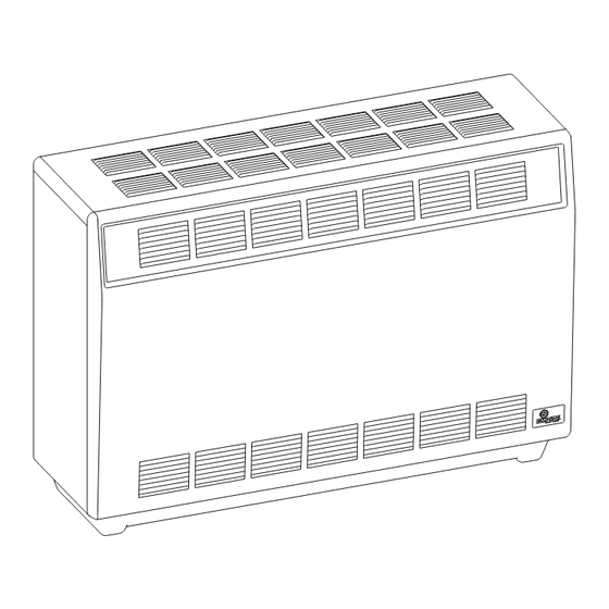
IMPORTANT SAFETY INFORMATION THIS IS A HEATING APPLIANCE DO NOT OPERATE THIS APPLIANCE WITHOUT FRONT PANEL INSTALLED. • Due to high temperatures, the room heater should be circulating air passageways of the room heater be kept located out of traffic and away from furniture and drap- clean. -
Page 4: Safety Information For Users Of Lp Gas
SAFETY INFORMATION FOR USERS OF LP-GAS Propane (LP-Gas) is a flammable gas which can cause fires by point with the members of your household. Someday and explosions. In its natural state, propane is odorless and when there may not be a minute to lose, everyone's safety colorless. -
Page 5: Introduction
4,500 feet (1370m), the manifold pressure is to be decreased from 4.0" w.c. (.996kPa) to 3.2" w.c. (.797kPa) for Natural Gas and from 10.0" w.c. (2.49kPa) to 8.0" w.c. (1.99kPa) for Propane Gas. SPECIFICATIONS Model RH-25 RH-35 Input BTU.HR (KW/H) 25,000 (7.3) 35,000 (10.3) Height 26"... -
Page 6: Gas Supply
GAS SUPPLY adequate, contact your local authorized installer for installation Recommended Gas Pipe Diameter or relocation. Pipe Length Schedule 40 Pipe Tubing, Type L Compounds used on threaded joints of gas piping shall be resistant Inside Diameter Outside Diameter to the action of liquefied petroleum gases. The gas lines must be Nat. -
Page 7: Clearances
CLEARANCES Clearances: When facing the front of the room heater the mini- Do not install in alcove or closet. No horizontal projection above mum clearances to combustible construction (material) are the heater permitted within 48 inches (122cm). following: Ceiling 48 inches (122cm). Rear of draft hood 2 inches (51mm). Right side 6 inches (152mm). -
Page 8: Vent Safety Shutoff System
VENT SAFETY SHUTOFF SYSTEM This heater must be properly connected to a venting system. This This room heater is equipped with a vent safety switch. The vent heater is equipped with a vent safety shutoff system. safety switch will cause gas flow to the pilot to “shut off” due to improper venting or a blocked flue. -
Page 9: Lighting Instructions
LIGHTING INSTRUCTIONS FOR YOUR SAFETY READ BEFORE LIGHTING WARNING: If you do not follow these instructions exactly, a fire or explosion may result causing property damage, personal injury, or loss of life. A. This appliance has a pilot which must be lighted by hand. •... -
Page 10: Pilot Flame Characteristics
PILOT FLAME CHARACTERISTICS The correct flame will be almost horizontal, blue and will extend past the thermocouple 1/4" (6mm). The flame will surround the thermocouple just below the tip. On Propane (LP-gas) slight yellow might occur where the pilot flame and the burner flame meet. Natural gas pilots require adjusting when the inlet pressure is above 5"... -
Page 11: Maintenance
MAINTENANCE To Remove Main Burner Cleaning Combustion Chamber 1. Disconnect the thermocouple and pilot supply line at the pilot A qualified serviceman should remove the chamber and apply air burner. pressure to the inside in order to clear all passageways. 2. -
Page 12: How To Order Repair Parts
PARTS LIST INDEX PART DESCRIPTION INDEX PART DESCRIPTION NUMBER NUMBER 11704 Inner Casing Assembly (RH-25-6) (USA) R-6096 Knob & Adaptor Set 15672 Inner Casing Assembly (RH-25-6) (Canada) 11700 Control Rod Bracket 11701 Inner Casing Assembly (RH-35-6) (USA) R-2706 ECO Switch... -
Page 13: Parts View
PARTS VIEW 12821-8-0907 Page 13... -
Page 14: Optional Blower Installation Instructions
When facing appliance, insert blower assembly into the left section of the casing (adjacent to the combustion chamber). For RH-25-(1, 2, 4, 5, 6) and RH-35-(1, 2, 4, 5, 6), route cord set through opening in casing back. The opening in casing back is located adjacent to gas control. - Page 15 Code, CSA C22.1, if an external electrical source is utilized. This appliance is equipped with a three-prong [grounding] plug for your protection against shock hazard and should be plugged directly into a properly grounded three-prong receptacle. Do not cut or remove the grounding prong from this plug. For an ungrounded receptacle, an adapter, which has two prongs and a wire for grounding, can be purchased, plugged into the ungrounded receptacle and its wire connected to the receptacle mounting screws.
Need help?
Do you have a question about the RH-25 and is the answer not in the manual?
Questions and answers