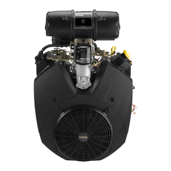
Kohler Command PRO CH940 Service Manual
Horizontal crankshaft
Hide thumbs
Also See for Command PRO CH940:
- Service manual (124 pages) ,
- Owner's manual (9 pages) ,
- Owner's manual (21 pages)
Table of Contents
Advertisement
CH940-CH1000
Service Manual
IMPORTANT:
Read all safety precautions and instructions carefully before operating equipment. Refer to operating
instruction of equipment that this engine powers.
Ensure engine is stopped and level before performing any maintenance or service.
2
Safety
3
Maintenance
5
Specifi cations
13
Tools and Aids
16
Troubleshooting
20
Air Cleaner/Intake
21
Fuel System
27
Governor System
28
Lubrication System
30
Electrical System
45
Disassembly/Inspection and Service
59
Reassembly
62 690 01 Rev. C
KohlerEngines.com
1
Advertisement
Table of Contents

Subscribe to Our Youtube Channel
Related Manuals for Kohler Command PRO CH940


Summary of Contents for Kohler Command PRO CH940
- Page 1 CH940-CH1000 Service Manual IMPORTANT: Read all safety precautions and instructions carefully before operating equipment. Refer to operating instruction of equipment that this engine powers. Ensure engine is stopped and level before performing any maintenance or service. Safety Maintenance Specifi cations Tools and Aids Troubleshooting Air Cleaner/Intake...
-
Page 2: Safety Precautions
Safety SAFETY PRECAUTIONS WARNING: A hazard that could result in death, serious injury, or substantial property damage. CAUTION: A hazard that could result in minor personal injury or property damage. NOTE: is used to notify people of important installation, operation, or maintenance information. CAUTION WARNING WARNING... -
Page 3: Maintenance Instructions
Have a Kohler authorized dealer perform this service. REPAIRS/SERVICE PARTS Kohler genuine service parts can be purchased from Kohler authorized dealers. To fi nd a local Kohler authorized dealer visit KohlerEngines.com or call 1-800-544-2444 (U.S. and Canada). 62 690 01 Rev. C... -
Page 4: Oil Recommendations
OIL RECOMMENDATIONS STORAGE If engine will be out of service for 2 months or more We recommend use of Kohler oils for best performance. follow procedure below. Other high-quality detergent oils (including synthetic) of API (American Petroleum Institute) service class SJ 1. - Page 5 Specifi cations Engine Dimensions with Heavy-Duty Air Cleaner Dimensions in millimeters. Inch equivalents shown in [ ]. 62 690 01 Rev. C KohlerEngines.com...
- Page 6 Specifi cations Engine Dimensions with Low-Profi le Air Cleaner Dimensions in millimeters. Inch equivalents shown in [ ]. KohlerEngines.com 62 690 01 Rev. C...
-
Page 7: Engine Identification Numbers
Lubricate threads with engine oil prior to assembly. Any and all horsepower (hp) references by Kohler are Certifi ed Power Ratings and per SAE J1940 & J1995 hp standards. Details on Certifi ed Power Ratings can be found at KohlerEngines.com. - Page 8 Specifi cations TORQUE SPECIFICATIONS CH940 CH960 CH980 CH1000 Control Panel M6 screw 10.7 N·m (95 in. lb.) into new holes 7.3 N·m (65 in. lb.) into used holes M5 screws 6.2 N·m (55 in. lb.) into new holes 4.0 N·m (35 in. lb.) into used holes Crankcase Breather Cover Fastener 5.7 N·m (51 in.
-
Page 9: Clearance Specifications
Specifi cations TORQUE SPECIFICATIONS CH940 CH960 CH980 CH1000 Oil Pickup Screen Mounting Screw 10.7 N·m (95 in. lb.) into new holes 7.3 N·m (65 in. lb.) into used holes Oil Pickup Tube Mounting Screw 10.7 N·m (95 in. lb.) into new holes 7.3 N·m (65 in. - Page 10 Specifi cations CLEARANCE SPECIFICATIONS CH940 CH960 CH980 CH1000 Connecting Rod Crankpin End I.D. @ 70°F 44.030/44.037 mm (1.7334/1.7337 in.) Max. Wear Limit 0.070 mm (0.0028 in.) Connecting Rod-to-Crankpin Running Clearance 0.030/0.055 mm (0.0012/0.0022 in.) Max. Wear Limit 0.070 mm (0.0028 in.) Connecting Rod-to-Crankpin Side Clearance 0.30/0.59 mm (0.0118/0.0232 in.) Connecting Rod-to-Piston Pin Running Clearance...
- Page 11 Specifi cations CLEARANCE SPECIFICATIONS CH940 CH960 CH980 CH1000 Cylinder Head Max. Out-of-Flatness 0.076 mm (0.003 in.) Governor Governor Cross Shaft-to-Crankcase Running Clearance 0.025/0.087 mm (0.0009/0.0034 in.) Governor Cross Shaft O.D. 7.963/8.000 mm (0.3135/0.3149 in.) 7.936 mm (0.3124 in.) Max. Wear Limit Governor Gear Shaft-to-Governor Gear Running Clearance 0.070/0.160 mm (0.0027/0.0063 in.) Governor Gear Shaft O.D.
-
Page 12: General Torque Values
Specifi cations GENERAL TORQUE VALUES English Fastener Torque Recommendations for Standard Applications Bolts, Screws, Nuts and Fasteners Assembled Into Cast Iron or Steel Grade 2 or 5 Fasteners Into Aluminum Size Grade 2 Grade 5 Grade 8 Tightening Torque: N·m (in. lb.) ± 20% 8-32 2.3 (20) 2.8 (25) - Page 13 Here is a list of tools and their source. SEPARATE TOOL SUPPLIERS Kohler Tools SE Tools Design Technology Inc. Contact your local Kohler source of 415 Howard St. 768 Burr Oak Drive supply. Lapeer, MI 48446 Westmont, IL 60559...
- Page 14 For reaming worn valve guides to accept replacement oversize valves. Can be used in low-speed drill press or with handle below for hand reaming. Design Technology Inc. Reamer Handle For hand reaming using Kohler 25 455 12-S reamer. DTI-K830 SE Tools KLR-82415 Valve Guide Service Kit (Courage, Aegis, Command, OHC) For servicing worn valve guides.
- Page 15 Tools and Aids FLYWHEEL HOLDING TOOL ROCKER ARM/CRANKSHAFT TOOL A fl ywheel holding tool can be made out of an old junk A spanner wrench to lift rocker arms or turn crankshaft fl ywheel ring gear and used in place of a strap wrench. may be made out of an old junk connecting rod.
-
Page 16: Troubleshooting Guide
Troubleshooting TROUBLESHOOTING GUIDE When troubles occur, be sure to check simple causes which, at fi rst, may seem too obvious to be considered. For example, a starting problem could be caused by an empty fuel tank. Some general common causes of engine troubles are listed below and vary by engine specifi cation. Use these to locate causing factors. - Page 17 Troubleshooting EXTERNAL ENGINE INSPECTION Engine Loses Power NOTE: It is good practice to drain oil at a location away ● Dirty air cleaner element. from workbench. Be sure to allow ample time for ● Engine overheated. complete drainage. ● Excessive engine load. ●...
-
Page 18: Crankcase Vacuum Test
Troubleshooting CRANKCASE VACUUM TEST WARNING WARNING Carbon Monoxide can cause severe nausea, Rotating Parts can cause severe injury. fainting or death. Stay away while engine is in operation. Avoid inhaling exhaust fumes. Engine exhaust gases contain poisonous carbon Keep hands, feet, hair, and clothing away from all monoxide. -
Page 19: Compression Test
Troubleshooting COMPRESSION TEST For Command Twins: A compression test is best performed on a warm engine. Clean any dirt or debris away from base of spark plug(s) before removing them. Be sure choke is off, and throttle is wide open during test. Compression should be at least 160 psi and should not vary more than 15% between cylinders. -
Page 20: Breather Tube
Air Cleaner/Intake NOTE: Operating engine with loose or damaged air AIR CLEANER cleaner components could cause premature These systems are CARB/EPA certifi ed and components wear and failure. Replace all bent or damaged should not be altered or modifi ed in any way. components. -
Page 21: Fuel Pump
FUEL LINE Disassembly and Reassembly. Low permeation fuel line must be installed on carbureted 3. Reconnect fuel lines to inlet and outlet fi ttings and Kohler Co. engines to maintain EPA and CARB secure with clamps. regulatory compliance. FUEL SYSTEM TESTS When engine starts hard or turns over but will not start, fuel system might be causing problems. - Page 22 Fuel System CARBURETOR Gasoline is extremely fl ammable and its vapors can WARNING explode if ignited. Store gasoline only in approved Explosive Fuel can cause fi res and severe containers, in well ventilated, unoccupied buildings, away burns. from sparks or fl ames. Spilled fuel could ignite if it comes in contact with hot parts or sparks from ignition.
- Page 23 Fuel System Engines in this series are equipped with a two-barrel, 4. Make sure air cleaner base and carburetor are side-draft carburetor with fi xed main jets on a matching securely fastened to engine using gaskets in good intake manifold. Carburetor features a self-relieving condition.
- Page 24 Fuel System Fuel Shut-off Solenoid Carburetor Adjustments Most carburetors are equipped with a fuel shut-off NOTE: Carburetor adjustments should be made only solenoid. Solenoid is attached to fuel bowl. Solenoid has after engine has warmed up. a spring-loaded pin that retracts when 12 volts is applied Carburetor is designed to deliver correct fuel-to-air to lead, allowing fuel fl...
- Page 25 Fuel System NOTE: Engines will have fi xed low idle or limiter caps 1. Perform removal procedures for appropriate air on idle fuel adjusting needles. Step 2 can only cleaner and carburetor outlined in Disassembly. be performed within limits allowed by cap. Do 2.
-
Page 26: High Altitude Operation
Install new cap. above 1219 meters (4000 ft.). To obtain high 18. Clean carburetor body, main jets, vent ports, seats, altitude kit information or to fi nd a Kohler etc., using a good commercially available carburetor authorized dealer visit KohlerEngines.com or call solvent. -
Page 27: Governor System
Governor System GOVERNOR Governed speed setting is determined by position of throttle control. It can be variable or constant, depending on engine application. Governor is designed to hold engine speed constant under changing load conditions. Most engines are equipped with a centrifugal fl... -
Page 28: Check Oil Level
Lubrication System This engine uses a full pressure lubrication system which delivers oil under pressure to crankshaft, camshaft, connecting rod bearing surfaces, and hydraulic valve lifters. A high-effi ciency gerotor oil pump maintains high oil fl ow and oil pressure, even at low speeds and high operating temperatures. -
Page 29: Oil Cooler
Lubrication System OIL COOLER NOTE: Oil cooler is mounted under cylinder shroud. Removal of cylinder shroud is necessary to access oil cooler. 1. Clean fi ns with a brush or compressed air. 2. Remove screws securing oil cooler and tilt to clean back side. -
Page 30: Spark Plugs
Electrical System SPARK PLUGS Inspection Inspect each spark plug as it is removed from cylinder CAUTION head. Deposits on tip are an indication of general Electrical Shock can cause injury. condition of piston rings, valves, and carburetor. Do not touch wires while engine is running. Normal and fouled plugs are shown in following photos: Normal Spark Plug Component and Details... - Page 31 Electrical System Carbon Fouled ELECTRONIC IGNITION SYSTEMS Ignition System Components Soft, sooty, black deposits indicate incomplete combustion caused by a restricted air cleaner, over rich Kill Switch/ carburetion, weak ignition, or poor compression. Off Position of Air Gap Key Switch Overheated Flywheel Magnet...
- Page 32 Electrical System Fixed Ignition System This system uses a capacitive discharge (CD) coil. Ignition timing and spark remains constant regardless of engine speed. Timing of spark is controlled by location of fl ywheel magnet group as referenced to engine TDC. A typical fi xed ignition system consists of: ●...
- Page 33 Electrical System Wire Diagram-15/20/25 Amp Regulated Battery Charging System with Fixed Timing, Five Pin Connector, Key Switch, and Fuse Green (Oil Sentry Blue Yellow ™ Pulse Signal) Violet White Black Key Switch To Battery To Accessory Ground To Rectifi er-Regulator Oil Sentry Light To Magneto...
- Page 34 Electrical System Digital Spark Advance Ignition (DSAI) System This system uses a digital microprocessor which is located in ignition modules. Ignition timing varies depending upon engine speed with this system. There are 2 inductive-style ignition modules that control ignition timing based on engine RPM.
- Page 35 Electrical System Wire Diagram-15/20/25 Amp Regulated Battery Charging System with DSAI Ignition and Four Pin Connector (LP-NG Kohler Power Systems Application) Green Orange Violet White Black Connector Polarity Ribs Battery Battery Positive Battery Negative Starter Solenoid Stud External Starter Rectifi er-Regulator Starter Rectifi...
- Page 36 Electrical System Wire Diagram-15/20/25 Amp Regulated Battery Charging System with DSAI Ignition and Five Pin Connector (Gasoline/LP-NG Non-Kohler Power Systems Application) Blue Green Orange Violet White Black Connector Polarity Ribs Battery Battery Positive Battery Negative Starter Solenoid Stud Starter Solenoid Tang...
- Page 37 Electrical System Electronic Ignition Systems Tests Special Tools Required: NOTE: Ignition tester must be used to test ignition on these engines. Use of any other tester can result in inaccurate fi ndings. Battery on unit must be fully charged and properly connected before performing tests (a battery that is hooked up or charged backward will crank engine but it won’t have spark).
- Page 38 Electrical System Test Timing Advance (DSAI only) 1. Make a line near edge of fl ywheel screen with a marking pen, chalk, or narrow tape. 2. Connect an automotive timing light to cylinder that had good spark. 3. Run engine at idle and use timing light beam to locate line on screen. Draw a line on blower housing next to line on screen.
-
Page 39: Battery Charging System
Electrical System BATTERY CHARGING SYSTEM NOTE: Observe following guidelines to avoid damage to electrical system and components: ● Make sure battery polarity is correct. A negative (-) ground system is used. ● Disconnect rectifi er-regulator plug and/or wiring harness plug before doing any electric welding on equipment powered by engine. - Page 40 Electrical System 15/20/25 Amp Battery Charging Systems NOTE: Always zero ohmmeter on each scale before testing to ensure accurate readings. Voltage tests should be made with engine running at 3600 RPM with no load. Battery must be good and fully charged. When problems occur in keeping battery charged or battery charges at high rate, charging system or battery might be causing problems.
- Page 41 Electrical System ELECTRIC STARTING MOTOR NOTE: Do not crank engine continuously for more than 10 seconds. Allow a 60 second cool down period between starting attempts. Failure to follow these guidelines can burn out starter motor. NOTE: If engine develops suffi cient speed to disengage starter but does not keep running (a false start), engine rotation must be allowed to come to a complete stop before attempting to restart engine.
- Page 42 Electrical System 5. Remove commutator end plate assembly, containing Solenoid Shift Starter Components brush holder, brushes, springs, and locking caps. Remove thrust washer from inside commutator end. 6. Remove frame from armature and drive end cap. 7. Remove drive lever pivot bushing and backing plate (if equipped) from end cap.
- Page 43 4 brushes and springs are serviced as a set. Use a new holes in metal clips must be up/out. Slide brush Kohler brush and spring kit if replacement is necessary. holder assembly down into place around commutator, and install positive (+) brush lead 1.
- Page 44 Electrical System 12. Install thru bolts and brush holder mounting screws. Torque bolts to 5.6-9.0 N·m (49-79 in. lb.) and brush holder mounting screws to 2.5-3.3 N·m (22-29 in. lb.). 13. Hook plunger behind upper end of drive lever and install spring into solenoid. Insert mounting screws through holes in drive end cap.
- Page 45 Disassembly/Inspection and Service WARNING Before working on engine or equipment, disable engine as Accidental Starts can cause severe injury or follows: 1) Disconnect spark plug lead(s). 2) Disconnect death. negative (–) battery cable from battery. Disconnect and ground spark plug lead(s) before servicing.
- Page 46 Disassembly/Inspection and Service Clean all parts thoroughly as engine is disassembled. Removing Control Bracket, Governor Springs, and Only clean parts can be accurately inspected Lever and gauged for wear or damage. There are many 1. Unhook governed idle and governor springs from commercially available cleaners that will quickly remove controls on main bracket and governor lever.
- Page 47 Disassembly/Inspection and Service Remove Oil Cooler Remove Oil Filter Housing and Oil Filter Adapter NOTE: New clamps are recommended any time NOTE: Further disassembly of oil fi lter housing disassembly is performed, or if clamps have assembly is not required unless being serviced been loosened (expanded) several times.
- Page 48 fl ywheel, crankshaft, and key if fl ywheel key is sheared or keyway is damaged. Inspect ring gear for cracks or damage. Kohler does not provide ring gear as a serviceable part. Replace fl ywheel if ring gear is damaged.
- Page 49 Disassembly/Inspection and Service Cylinder Head Components Gasket Valve Cylinder Head Pipe Plug Spacer Washer Spark Plug Valve Stem Seal Valve Spring Hydraulic Lifter Valve Spring Retainer Push Rod Valve Spring Keeper Rocker Arm Rocker Arm Pivots Valve Cover Gasket Valve Cover Grommet Electric Fuel Pump Remove Valve Covers and Fuel Pump...
-
Page 50: Exhaust Valve
● Valve spring retainers. damage. If lifters need to be replaced, apply a liberal ● Valve springs. coating of Kohler lubricant to base of each new lifter ● Valve spring caps. before it is installed. ● Intake and exhaust valves (mark position). - Page 51 Disassembly/Inspection and Service After cleaning, check fl atness of cylinder head and Valve Seat Inserts corresponding top surface of crankcase using a surface Hardened steel alloy intake and exhaust valve seat plate or piece of glass and feeler gauge. Maximum inserts are press fi...
- Page 52 Disassembly/Inspection and Service Breather/Closure Plate/Oil Reservoir Components Closure Plate Gerotor Gears Oil Pump O-Ring Oil Pump Housing Relief Valve Baffl e Pickup Tube Clamp Inlet Seal Pickup Screen Oil Reservoir Drain Plug Gasket Crankshaft Bearing Closure Plate Gasket Dipstick Dipstick Tube (PTO) Breather Assembly Breather Gasket...
- Page 53 Disassembly/Inspection and Service 1. Make sure recess in closure plate for oil pump Remove Closure Plate Assembly gerotor gears is clean. 1. Remove screws securing closure plate to crankcase. 2. Lubricate oil pump gerotor gears with grease 2. Locate protruding tabs on closure plate. Carefully (Lubriplate ®...
- Page 54 Disassembly/Inspection and Service Crankcase Components Camshaft Locking Tab Regulating Pin Governor Gear Lifter Feed Cover Cross Shaft Lifter Feed Cover Governor Yoke Gasket Connecting Rod End Crankshaft Connecting Rod Piston Pin Piston Pin Retainer Piston Piston Ring Set Oil Seal Crankshaft Bearing (Flywheel) Remove Camshaft...
- Page 55 Disassembly/Inspection and Service Scratches on rings and pistons are caused by abrasive Piston and Rings material such as carbon, dirt, or pieces of hard metal. Inspection Detonation damage occurs when a portion of fuel charge Piston and Rings Components and Details ignites spontaneously from heat and pressure shortly after ignition.
- Page 56 Disassembly/Inspection and Service 3. Top compression ring (top groove): Install top ring Inspect crankshaft keyways. If they are worn or chipped, using a piston ring expander. Make sure replacement of crankshaft will be necessary. identifi cation mark is up or colored dye stripe Inspect crankpin for score marks or metallic pickup.
- Page 57 23°-33° Crosshatch use a press and support casting surface around bearing fl ange. Do not press against or support NOTE: Kohler pistons are custom-machined to exacting by gasket/outer perimeter surface. tolerances. When oversizing a cylinder, it should be machined exactly 0.25 mm (0.010 in.) or Crankcase 0.50 mm (0.020 in.) over new diameter.
- Page 58 Disassembly/Inspection and Service Clean Cylinder Bore After Honing Proper cleaning of cylinder walls following boring and/ or honing is very critical to a successful overhaul. Machining grit left in cylinder bore can destroy an engine in less than 1 hour of operation after a rebuild. Final cleaning operation should always be a thorough scrubbing with a brush and hot, soapy water.
- Page 59 Reassembly Crankcase Components Camshaft Locking Tab Regulating Pin Governor Gear Lifter Feed Cover Cross Shaft Lifter Feed Cover Governor Yoke Gasket Connecting Rod End Crankshaft Connecting Rod Piston Pin Piston Pin Retainer Piston Piston Ring Set Oil Seal Crankshaft Bearing (Flywheel) NOTE: Make sure engine is assembled using all 3.
- Page 60 Reassembly Install Governor Shafts, Seal, and Governor Gear Install Crankshaft Carefully slide fl ywheel end of crankshaft through Governor Components and Details bearing in crankcase. Install Connecting Rods with Pistons and Rings Piston Details Side 1 Side 2 Top of Piston NOTE: Cylinders are numbered on crankcase.
- Page 61 Reassembly Breather/Closure Plate/Oil Reservoir Components Closure Plate Gerotor Gears Oil Pump O-Ring Oil Pump Housing Relief Valve Baffl e Pickup Tube Clamp Inlet Seal Pickup Screen Oil Reservoir Drain Plug Gasket Crankshaft Bearing Closure Plate Gasket Dipstick Dipstick Tube (PTO) Breather Assembly Breather Gasket Filter...
- Page 62 Reassembly Several color coded shims are available: Install Closure Plate Assembly White: 0.69215/0.73025 mm (0.02725/0.02875 in.) Torque Sequence Blue: 0.74295/0.78105 mm (0.02925/0.03075 in.) Red: 0.79375/0.83185 mm (0.03125/0.03275 in.) Yellow: 0.84455/0.88265 mm (0.03325/0.03475 in.) Green: 0.89535/0.99345 mm (0.03525/0.03675 in.) Gray: 0.94615/0.98425 mm (0.03725/0.03875 in.) Black: 0.99695/1.03505 mm (0.03925/0.04075 in.) 4.
- Page 63 Reassembly 1. Use bolts with heads removed, or a similar item as Check Crankshaft End Play temporary alignment pins and install into 2 center Set engine on base and use a dial indicator to check holes on ends. crankshaft end play to 0.30/1.50 mm (0.011/0.059 in.). 2.
- Page 64 Reassembly Cylinder Head Components Gasket Valve Cylinder Head Pipe Plug Spacer Washer Spark Plug Valve Stem Seal Valve Spring Hydraulic Lifter Valve Spring Retainer Push Rod Valve Spring Keeper Rocker Arm Rocker Arm Pivots Valve Cover Gasket Valve Cover Grommet Install Hydraulic Lifters Valve Stem Seals NOTE: Hydraulic lifters should always be installed in...
- Page 65 Reassembly Install Cylinder Heads Install Push Rods and Rocker Arms NOTE: Push rods should always be installed in same Torque Sequence position as before disassembly. 1. Note mark or tag identifying push rod as either intake or exhaust and cylinder 1 or 2. Dip ends of push rods in engine oil and install, making sure each push rod ball seats in its hydraulic lifter socket.
- Page 66 Reassembly Oil Cooler/Filter Components Install Intake Manifold Torque Sequence 1. Install new intake manifold gaskets so notched section is inward and points toward fl ywheel side. 2. Mount intake manifold to cylinder heads. Make sure gaskets remain in proper position. Torque screws in 2 stages using sequence shown, fi...
- Page 67 Reassembly Flywheel/Ignition Components Rectifi er-Regulator Ignition Module Washer Flywheel Screw Special Washer Wire Harness Clamp Debris Screen Stiffener Hex Stud Flywheel Magnet Stator Backing Shroud Woodruff Key Install Backing Shroud Assembly Install Stator, Wiring Harness, and Rectifi er- Regulator NOTE: New hose clamps are recommended for reassembly, or if clamps have been loosened 1.
- Page 68 Reassembly Install Flywheel Install Cooling Fan and Debris Screen CAUTION CAUTION Damaging Crankshaft and Flywheel Can Failure to utilize or reassemble debris screen cause personal injury. as designed could result in debris screen failure and serious personal injury. Using improper procedures can lead to broken Cooling Fan and Debris Screen Components fragments.
- Page 69 Reassembly External Engine Components O O P Oil Filter Oil Filter Nipple Oil Filter Cup Valve Spring Cup Spring Valve Oil Filter Housing Valley Baffl e Outer Cylinder Baffl e Electric Starter Cylinder Shroud Blower Housing Fixed Guard Oil Sentry O-ring ™...
- Page 70 Reassembly Install Oil Cooler Install Carburetor 1. Connect hoses between oil fi lter adapter and oil cooler. Secure with new clamps. WARNING Explosive Fuel can cause fi res and severe 2. Align oil cooler with bosses in backing shroud burns. assembly.
- Page 71 Reassembly If individual throttle/choke lever control linkages were Install Governor Lever disconnected during disassembly, reconnect them based Install governor lever onto governor shaft and connect on operating direction of control cables to be used. throttle linkage with black clip. Do not tighten governor Hole A is used for Outer Pull control cable actuation.
- Page 72 Reassembly Install Oil Sentry (if equipped) Install Muffl er ™ 1. Apply pipe sealant with Tefl on (Loctite 592™ 1. Install new exhaust gaskets onto exhaust studs. ® ® ® Thread Sealant or equivalent) to Oil Sentry threads 2. Install port liners (if equipped). Attach muffl er and ™...
- Page 73 62 690 01 Rev. C KohlerEngines.com...
- Page 74 KohlerEngines.com 62 690 01 Rev. C...
- Page 75 62 690 01 Rev. C KohlerEngines.com...
- Page 76 © 2011 by Kohler Co. All rights reserved. KohlerEngines.com 62 690 01 Rev. C...
Need help?
Do you have a question about the Command PRO CH940 and is the answer not in the manual?
Questions and answers