Kohler CH940 Service Manual
Horizontal crankshaft
Hide thumbs
Also See for CH940:
- Service manual (88 pages) ,
- Owner's manual (9 pages) ,
- Owner's manual (21 pages)
Advertisement
Table of Contents
- 1 Table of Contents
- 2 Section 1. Safety and General Information
- 3 Section 2. Tools & Aids
- 4 Section 3. Troubleshooting
- 5 Section 4. Air Cleaner and Air Intake System
- 6 Section 4 Air Cleaner and Air Intake System
- 7 Section 5. Fuel System and Governor
- 8 Section 6. Lubrication System
- 9 Section 7. Electrical System and Components
- 10 Section 8. Disassembly
- 11 Section 9. Inspection and Reconditioning
- 12 Section 10. Reassembly
- Download this manual
Advertisement
Table of Contents

Related Manuals for Kohler CH940


Summary of Contents for Kohler CH940
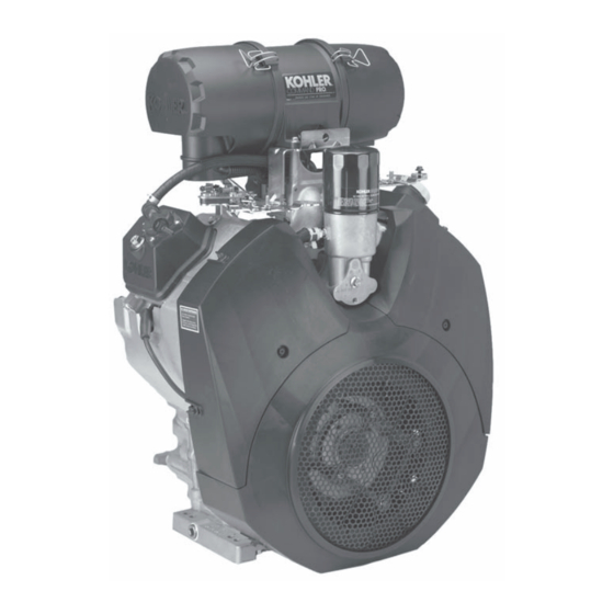
- Page 1 ERVICE ANUAL COMMAND PRO CH940-CH980 ORIZONTAL RANKSHAFT...
-
Page 2: Table Of Contents
Section 1. Safety and General Information ... Section 2. Tools & Aids ... Section 3. Troubleshooting ... Section 4. Air Cleaner and Air Intake System ... Section 5. Fuel System and Governor ... Section 6. Lubrication System ... Section 7. Electrical System and Components ... Section 8. -
Page 3: Section 1. Safety And General Information
Safety and General Information Safety Precautions To ensure safe operation please read the following statements and understand their meaning. Also refer to your equipment manufacturer's manual for other important safety information. This manual contains safety precautions which are explained below. Please read carefully. WARNING Warning is used to indicate the presence of a hazard that can cause severe personal injury, death, or substantial property damage if the warning is ignored. - Page 4 Section 1 Safety and General Information WARNING Explosive Fuel can cause fires and severe burns. Do not fill the fuel tank while the engine is hot or running Explosive Fuel! Gasoline is extremely flammable and its vapors can explode if ignited. Store gasoline only in approved containers, in well ventilated, unoccupied buildings, away from sparks or flames.
- Page 5 Year 2007 2008 Figure 1-2. Explanation of Engine Identification Numbers. Safety and General Information Figure 1-1. Engine Identification Decal Location. C H 980 S CH940-0001 CH960-0001 CH980-0001 Complete Spec. Number (Incorporating Model No. with Variation No. of Basic Spec.) 3705810334...
- Page 6 Gasoline/Alcohol Blends Gasohol (up to 10% ethyl alcohol, 90% unleaded gasoline by volume) is approved as a fuel for Kohler engines. Other gasoline/alcohol blends including E20 and E85 are not to be used and not approved. Any failures resulting from use of these fuels will not be warranted.
- Page 7 Every 600 Hours • Replace spark plugs. ¹Perform these maintenance procedures more frequently under extremely dusty, dirty conditions. Have a Kohler Engine Service Dealer perform this service. Storage If the engine will be out of service for 30 days or more, use the following storage procedure.
- Page 8 Section 1 Safety and General Information Figure 1-4. Typical CH PRO Series Engine Dimensions with Heavy-Duty Air Cleaner. Dimensions in millimeters. Inch equivalents shown in [ ].
- Page 9 General Specifications¹ Power (@ 3600 RPM, exceeds Society of Automotive Engineers-Small Engine Test Code J1940.) CH940 ... 25.4 kW (34 HP) CH960 ... 26.9 kW (36 HP) CH980 ... 28.3 kW (38 HP) Bore ... 90 mm (3.54 in.) Stroke ... 78.5 mm (3.1 in.) Displacement ...
- Page 10 Section 1 Safety and General Information Carburetor, Intake Manifold, and Air Cleaner Intake Manifold Mounting Fastener Torque Torque (Using Sequence) in Two Stages ... first to 16.9 N·m (150 in. lb.) Carburetor/Air Cleaner Mounting Nut Torque ... 7.9 N·m (70 in. lb.) Air Cleaner Mounting Screw Torque (Into Intake Manifold) ...
- Page 11 Crankshaft Bore (In Closure Plate) - New, Without Bearing ... 50.025/50.00 mm (1.9694/1.9685 in.) Crankshaft to Sleeve Bearing (In Closure Plate) Running Clearance - New ... 0.040/0.167 mm (0.0015/0.0065 in.) Flywheel End Main Bearing Journal O.D. - New ... 44.978/45.00 mm (1.770/1.771 in.) O.D.
- Page 12 Section 1 Safety and General Information Grass Screen Hex Stud Torque ... 9.9 N·m (88 in. lb.) Mounting Screw Torque ... 9.9 N·m (88 in. lb.) Front Drive Shaft Screw Torque (Into Flywheel) ... 24.4 N·m (216 in. lb.) Governor Governor Cross Shaft-to-Crankcase Running Clearance ...
- Page 13 Top Compression Ring-to-Groove Side Clearance ... 0.04/0.08 mm (0.0015/0.0031 in.) Middle Compression Ring-to-Groove Side Clearance ... 0.04/0.08 mm (0.0015/0.0031 in.) Oil Control Ring-to-Groove Side Clearance ... 0.03/0.19 mm (0.0011/0.0074 in.) Top and Center Compression Ring End Gap New Bore ... 0.30/0.55 mm (0.011/0.021 in.) Used Bore (Max.) ...
- Page 14 Section 1 Safety and General Information Valve Guide Reamer Size Standard ... 7.048 mm (0.2775 in.) 0.25 mm O.S..7.298 mm (0.2873 in.) Nominal Valve Face Angle ... 45° General Torque Values Metric Fastener Torque Recommendations for Standard Applications Tightening Torque: N·m (in.
- Page 15 English Fastener Torque Recommendations for Standard Applications Tightening Torque: N·m (in. lb.) + or - 20% Bolts, Screws, Nuts and Fasteners Assembled Into Cast Iron or Steel Grade 2 Size 8-32 2.3 (20) 10-24 3.6 (32) 10-32 3.6 (32) 1/4-20 7.9 (70) 1/4-28 9.6 (85)
-
Page 16: Section 2. Tools & Aids
By using tools designed for the job, you can properly service engines easier, faster, and safer! In addition, you’ll increase your service capabilities and customer satisfaction by decreasing engine downtime. Here is the list of tools and their source. Separate Tool Suppliers: Kohler Tools Contact your source of supply. &... - Page 17 Section 2 Tools & Aids ) . t c i l t f i l l a c i l e t f i t i & l l a n i l i r e l i o . e r i f i i f i i t c...
- Page 18 - l e i l i ® e t i l i o s i s e t i ® ® e t i e t i ® e t i ® ® e t i ) t f . r e , s t s i l s i r...
- Page 19 4. Use a flat washer with the correct I.D. to slip on the capscrew and approximately 1” O.D. (Kohler Part No. 12 468 05-S). Assemble the capscrew and washer to the joint surface of the rod, as shown in Figure 2-2.
-
Page 20: Section 3. Troubleshooting
Troubleshooting Guide When troubles occur, be sure to check the simple causes which, at first, may seem too obvious to be considered. For example, a starting problem could be caused by an empty fuel tank. Some general common causes of engine troubles are listed below. - Page 21 Section 3 Troubleshooting Engine Knocks 1. Excessive engine load. 2. Low crankcase oil level. 3. Old or improper fuel. 4. Internal wear or damage. 5. Hydraulic lifter malfunction. 6. Quality of fuel. 7. Incorrect grade of oil. Engine Loses Power 1.
- Page 22 Basic Engine Tests Crankcase Vacuum Test A partial vacuum should be present in the crankcase when the engine is operating. Pressure in the crankcase (normally caused by a clogged or improperly assembled breather) can cause oil to be forced out at oil seals, gaskets, or other available spots.
- Page 23 Section 3 Troubleshooting Compression Test A compression test is best performed on a warm engine. Clean any dirt or debris away from the base of the spark plugs before removing them. Be sure the choke is off, and the throttle is wide open during the test.
-
Page 24: Section 4. Air Cleaner And Air Intake System
Air Cleaner and Air Intake System Air Cleaners General These engines use a heavy-duty style air cleaner as shown in Figure 4-1, consisting of a cylindrical housing attached to the carburetor and intake manifold. The air cleaner housing contains a paper element and inner element, designed for longer service intervals. -
Page 25: Section 4 Air Cleaner And Air Intake System
4. Do not wash the paper element and inner element or use compressed air, this will damage the elements. Replace dirty, bent, or damaged elements with new genuine Kohler elements as required. Handle the new elements carefully; do not use if the sealing surfaces are bent or damaged. -
Page 26: Section 5. Fuel System And Governor
. Gasoline/Alcohol blends Gasohol (up to 10% ethyl alcohol, 90% unleaded gasoline by volume) is approved as a fuel for Kohler engines. Other gasoline/alcohol blends including E20 and E85 are not to be used and not approved. Any failures resulting from use of these fuels will not be warranted. - Page 27 Section 5 Fuel System and Governor Fuel System Tests When the engine starts hard, or turns over but will not start, it is possible that the problem is in the fuel system. To find out if the fuel system is causing the problem, perform the following tests. Troubleshooting –...
- Page 28 Figure 5-2. Optional Electric Fuel Pump. Fuel Pump - Replacement Replacing the Mechanical Fuel Pump The mechanical fuel pump is an integral part of the valve cover assembly and not serviced separately. See Figure 5-1. 1. Disconnect the fuel lines from the inlet and outlet fittings.
- Page 29 Section 5 Fuel System and Governor Troubleshooting – Carburetor Related Causes Condition 1. Engine starts hard, runs roughly, or stalls at idle speed. 2. Engine runs rich (indicated by black, sooty exhaust smoke, misfiring, loss of speed and power, governor hunting, or excessive throttle opening).
- Page 30 Have a container ready to catch the fuel. 2. Wipe the tip of the solenoid with a shop towel or blow it off with compressed air, to remove any remaining fuel. Take the solenoid to a location with good ventilation and no fuel vapors present.
- Page 31 Section 5 Fuel System and Governor Low Idle Fuel Adjusters (with Limiters) Bowl Vent Figure 5-5. Carburetor Adjustment Locations. Low Idle Fuel Adjustment NOTE: Engines will have fixed low idle or limiter caps on the two idle fuel adjusting needles. Step 3 can only be performed within the limits allowed by the cap.
- Page 32 Hold/Pull Governor Lever Back Governor Spring Must Be Loose In Slot Figure 5-8. Checking Spring Looseness. 3. Hold the governor lever away from the carburetor so the throttle lever is against the idle speed (RPM) adjustment screw of the carburetor. Start the engine and allow to warm up, then adjust the screw to set approximately 1200 RPM.
- Page 33 Section 5 Fuel System and Governor • Inspect the fuel inlet needle and seat for wear or damage. • The choke plate is spring loaded. Check to make sure it moves freely on the shaft. NOTE: The main and slow jets are fixed and side specific and can be removed if required.
- Page 34 Figure 5-16. Checking Float Height. 7. Hold the carburetor body so the float assembly hangs vertically and rests lightly against the fuel inlet needle. The inlet needle should be fully seated but the center pin of the needle (on retainer clip end) should not be depressed. Check the float height adjustment.
- Page 35 Section 5 Fuel System and Governor 2. Remove the float pin screw and lift out the old float, pin, and inlet needle. See Figure 5-19. Discard all the old parts. The seat for the inlet needle is not serviceable, and should not be removed.
- Page 36 6. Clean the carburetor body, main jets, vent ports, seats, etc., using a good commercially available carburetor solvent. Keep away from plastic or rubber parts if non-compatible. Use clean, dry compressed air to blow out the internal channels and ports. Do not use metal tools or wire to clean orifices and jets.
- Page 37 Section 5 Fuel System and Governor 14. Hold the carburetor body so the float assembly hangs vertically and rests lightly against the fuel inlet needle. The inlet needle should be fully seated but the center pin of the needle (on retainer clip end) should not be depressed.
- Page 38 7. Insert the new bushing through the new choke lever from the outside, and start the bushing in the outer shaft bore. Position the choke lever so the protruding boss on the carburetor housing is between the two stops formed in the choke lever. See Figure 5-30.
- Page 39 Section 5 Fuel System and Governor Figure 5-34. Installing Choke Plate. 12. Check for proper operation and free movement of the parts. Install the new cap. Always use new gaskets when servicing or reinstalling carburetors. Repair kits are available which include new gaskets and other components. Service/repair kits available for Keihin BK two-barrel carburetors and affiliated components are: Carburetor Overhaul Kit...
- Page 40 1. Carburetor Body Subassembly 2. Idle Speed Screw 3. Idle Speed Spring 4. Screw 5. Ground Lead 6. Retaining Washer 7. Slow Jet - RH Side 8. Slow Jet - LH Side 9. O-Ring (Slow Jet) (2) 10. Fuel Bowl 11.
- Page 41 Section 5 Fuel System and Governor • One end of the cross shaft protrudes through the crankcase. The rotating action of the cross shaft is transmitted to the throttle lever of the carburetor through the external throttle linkage. See Figure 5-36. Governor Lever Governed...
-
Page 42: Section 6. Lubrication System
R E C O M M E N D E D S A E V I S C O S I T Y G R A D E S 10W-30 5W-20, 5W-30 Kohler 10W-30 °F -20 °C -30 TEMPERATURE RANGE EXPECTED BEFORE NEXT OIL CHANGE * Use of synthetic oil having 5W-20 or 5W-30 rating is acceptable, up to 4°C (40°F) - Page 43 Section 6 Lubrication System Checking Oil Level The importance of checking and maintaining the proper oil level in the crankcase cannot be overemphasized. Check oil BEFORE EACH USE as follows: 1. Make sure the engine is stopped, level, and is cool so the oil has had time to drain into the sump.
- Page 44 Replace the oil filter seasonally (150 hours), or at least every other oil change (every 300 hours of operation). Always use a genuine Kohler oil filter. The oil filter on most engines is located on top of the crankcase between the cylinders. Some models use a remote mounted oil filter.
- Page 45 Section 6 Lubrication System Service Oil Cooler These engines are equipped with an oil cooler mounted under the No. 2 side cylinder shroud, separate from the oil filter. See Figure 6-9. Cooler Cylinder Shroud Figure 6-9. Oil Cooler. Inspect and clean the oil cooler every 150 hours of operation (more frequently under severe conditions).
- Page 46 Installation The Oil Sentry™ pressure switch is installed in the closure plate pressure port. See Figure 6-12. On engines not equipped with Oil Sentry™ the installation hole is sealed with a 1/8-27 N.P.T.F. pipe plug. To install the switch, follow these steps: 1.
-
Page 47: Section 7. Electrical System And Components
The engine is equipped with the following spark plugs: Type: The standard spark plug is a Champion XC10YC (Kohler Part No. 62 132 04-S). Equivalent alternate brand plugs can also be used. Gap: 0.76 mm (0.030 in.) Thread Size:... - Page 48 Section 7 Electrical System and Components Normal: A plug taken from an engine operating under normal conditions will have light tan or gray colored deposits. If the center electrode is not worn, a plug in this condition could be set to the proper gap and reused.
- Page 49 Battery General A 12-volt battery with 400 cold cranking amps (cca) is generally recommended for starting in all conditions. A smaller capacity battery is often sufficient if an application is started only in warmer temperatures. Refer to the following table for minimum capacities based on anticipated ambient temperatures.
- Page 50 Section 7 Electrical System and Components Electronic CD Ignition System Kill Switch or ‘‘Off’’ Position of Key Switch Figure 7-3. Capacitive Discharge (Fixed Timing) Ignition System. Operation of CD Ignition System Capacitive Discharge with Fixed Timing This system (Figure 7-3) consists of the following components: •...
- Page 51 Electrical System and Components 2. Test for spark on both cylinders with Kohler ignition tester (see Section 2). Disconnect one spark plug lead and connect it to the post terminal of the tester.
- Page 52 Section 7 Electrical System and Components 15/20/25 Amp Regulated Charging System Figure 7-5. 25 Amp Stator and 20/25 AmpRectifier- Figure 7-6. 15 Amp Stator and Rectifier-Regulator. Regulator. NOTE: 20 amp charging systems use a 15 amp stator with a 25 amp rectifier-regulator. Figure 7-7.
- Page 53 Section 7 Electrical System and Components Figure 7-8. Wiring Diagram15/20/25 Amp Regulated Battery Charging System with Fixed Timing, Five Pin Connector, Key Switch, and Fuse.
- Page 54 Section 7 Electrical System and Components Stator The stator is mounted on the crankcase behind the flywheel. Follow the procedures in Section 9 - Disassembly and Section 11 - Reassembly if stator replacement is necessary. Rectifier-Regulator The rectifier-regulator is mounted on the backing shroud assembly.
- Page 55 5. Plug the tester into the proper AC outlet/power for tester being used. Turn on the power switch. The POWER light should be illuminated and one of the four status lights may be on as well. See Figure 7-12. This does not represent the condition of the part.
- Page 56 Section 7 Electrical System and Components Troubleshooting Guide 15/20/25 Amp Battery Charging Systems When problems occur in keeping the battery charged or the battery charges at too high a rate, the problem can usually be found somewhere in the charging system or with the battery. NOTE: Always zero ohmmeter on each scale before testing to ensure accurate readings.
- Page 57 DC Voltmeter Figure 7-15. Connections for Testing Charging System. Electric Starting Motors The engines in this series use solenoid shift starters. A Delco-Remy solenoid shift starter is typically used. Starting Motor Precautions NOTE: Do not crank the engine continuously for more than 10 seconds at a time.
- Page 58 Section 7 Electrical System and Components Troubleshooting Guide – Starting Difficulties Problem Possible Fault Battery Starter Wiring Does Not Energize Starter Switch or Solenoid Battery Brushes Starter Energizes but Turns Slowly Transmission Engine Delco-Remy Starters Figure 7-16. Completed Delco-Remy Starter. Starter Disassembly 1.
- Page 59 Figure 7-18. Solenoid Removed from Starter. Figure 7-19. Removing Plunger. 4. Remove the two thru (larger) bolts. See Figure 7-20. Figure 7-20. Removing Thru Bolts. 5. Remove the commutator end plate assembly, containing the brush holder, brushes, springs, and locking caps. Remove the thrust washer from inside the commutator end.
- Page 60 Section 7 Electrical System and Components 8. Take out the drive lever and pull the armature out of the drive end cap. See Figure 7-24. 9. Remove the thrust washer from the armature shaft. See Figure 7-24. Figure 7-24. Armature and Lever Removed. 10.
- Page 61 Inspection Drive Pinion Check and inspect the following areas: a. The pinion teeth for abnormal wear or damage. b. The surface between the pinion and the clutch mechanism for nicks, or irregularities which could cause seal damage. c. Check the drive clutch by holding the clutch housing and rotating the pinion.
- Page 62 Electrical System and Components Brush Replacement The brushes and springs are serviced as a set (4). Use a new Kohler Brush and Spring Kit, if replacement is necessary. 1. Perform steps 1-5 in Starter Disassembly. 2. Remove the two screws securing the brush holder assembly to the end cap (plate).
- Page 63 3. Install the offset thrust (stop) washer so the smaller offset of the washer faces the retainer/ collar. See Figure 7-34. Figure 7-34. Installing Thrust Washer. 4. Apply a small amount of oil to the bearing in the drive end cap, and install the armature with the drive pinion.
- Page 64 Section 7 Electrical System and Components 9. Install the flat thrust washer onto the commutator end of the armature shaft. See Figure 7-38. Thrust Washer Figure 7-38. Installing Thrust Washer. 10. Starter reassembly when replacing the Brushes/ Brush Holder Assembly: a.
- Page 65 d. Hold the starter assembly vertically on the end housing, and carefully place the tool (with extension) and assembled original brush holder assembly onto the end of the armature shaft. Slide the brush holder assembly down into place around the commutator, install the positive (+) brush lead grommet in the cutout of the frame.
- Page 66 Section 7 Electrical System and Components Solenoid Test Procedure Solenoid Shift Style Starters Disconnect all leads from the solenoid including the positive brush lead attached to the lower stud terminal. Remove the mounting hardware and separate the solenoid from the starter for testing. Test 1.
- Page 67 Test 4. Solenoid Hold-In Coil/Contact Continuity Test. Use an ohmmeter set to the audible or Rx2K scale, and connect the two ohmmeter leads to the two large post terminals. Perform the preceding test (3) and check for continuity. See Figure 7-49. The meter should indicate continuity.
-
Page 68: Section 8. Disassembly
WARNING: Accidental Starts! Disabling engine. Accidental starting can cause severe injury or death. Before working on the engine or equipment, disable the engine as follows: 1) Disconnect the spark plug lead(s). 2) Disconnect negative (-) battery cable from battery. General Clean all parts thoroughly as the engine is disassembled. - Page 69 Section 8 Disassembly Shut Off Fuel Supply Drain Oil from Crankcase and Remove Oil Filter 1. Clean the oil filter and housing area. Remove and discard the oil filter. See Figure 8-2. Figure 8-2. Removing Oil Filter. 2. Remove the dipstick and one of the oil drain plugs.
- Page 70 Remove Electric Starter Motor 1. Disconnect the leads from the starter. 2. Remove the two hex flange screws and starter. See Figure 8-7. Mounting Screws Figure 8-7. Removing Electric Starter. Remove Air Cleaner Assembly 1. Disconnect the breather hose from the air cleaner, and the formed vent hose from the vent port on the carburetor.
- Page 71 Section 8 Disassembly Removing Control Bracket, Governor Springs, and Lever 1. Unhook the governed idle and governor springs from the controls on the main bracket and governor lever. Note the color, location and position of each. See Figure 8-11. 2. Disconnect the throttle linkage and dampening spring from the governor lever at the small bushing.
- Page 72 Remove Oil Sentry ™ (If Equipped) 1. Disconnect the lead from the Oil Sentry ™ 2. Remove the Oil Sentry switch from the closure plate. See Figure 8-15. Pressure Figure 8-15. Oil Sentry ™ Switch Location in Closure Plate. Remove Baffles and Intake Manifold 1.
- Page 73 Section 8 Disassembly Remove Oil Cooler 1. Remove the two oil cooler mounting screws. Do not lose any washers (if used). See Figure 8-19. Figure 8-19. Removing Oil Cooler Mounting Screws. 2. Loosen the clamps and disconnect each of the hoses from the oil cooler.
- Page 74 c. Remove the rubber valve and spring from the cup. See Figure 8-24. Valve Spring Figure 8-24. Rubber Valve and Spring Removed from Cup. 2. Remove the screw securing the oil filter adapter and individual O-Rings to the crankcase, then carefully separate the parts.
- Page 75 Section 8 Disassembly Mounting Mounting Screws Screws Figure 8-29. Removing Fan. Remove Flywheel 1. Use a flywheel strap wrench or holding tool (see Section 2) to hold the flywheel and loosen the hex flange screw securing the flywheel to the crankshaft.
- Page 76 Molded Clips Mounting Screws Figure 8-33. Removing Stator. 4. Unhook the wiring harness from the molded clips if it is being serviced separately. See Figure 8-34. Wiring Harness Molded Clip Molded Clip Figure 8-34. Removing Wiring Harness. Remove Backing Shroud Assembly 1.
- Page 77 Section 8 Disassembly Electric Fuel Pump 1. Removal will be determined based on mounted location and application. Disconnect the lead connections, fuel line connections, and mounting hardware as required. Properly contain any remaining fuel. Valve Covers 1. Remove the screw and grommet securing each valve cover.
- Page 78 Figure 8-42. Removing Hydraulic Lifters. Figure 8-43. Match Numbers on Cylinder Barrel and Heads. Disassemble Cylinder Heads 1. Remove the two hex flange screws, rocker arm pivots, and rocker arms from the cylinder head. See Figure 8-44. Figure 8-44. Removing Rocker Arms. 2.
- Page 79 Section 8 Disassembly NOTE: These engines use valve stem seals on the intake and exhaust valves. Use a new seal whenever valves are removed, or if the seal is deteriorated in any way. Never reuse an old seal. 4. Repeat the above procedure for the other cylinder head.
- Page 80 Remove Closure Plate Assembly 1. Remove the fourteen hex flange screws securing the closure plate to the crankcase. See Figure 8-52. Figure 8-52. Removing Closure Plate Screws. 2. Locate the two protruding tabs on the closure plate. Carefully tap to break the gasket seal. Do not pry on the sealing surfaces as this could cause leaks.
- Page 81 Section 8 Disassembly Figure 8-57. Remove Connecting Rod Caps. NOTE: The cylinders are numbered on the crankcase. Use the numbers to mark each end cap, connecting rod and piston for reassembly. Do not mix end caps and connecting rods. 2. Carefully remove the connecting rod and piston assembly from the cylinder bore.
- Page 82 Remove Governor Yoke, Cross Shaft, and Seal 1. Remove the two mounting screws securing the yoke to the governor cross shaft. See Figure 8-61. Figure 8-61. Removing Cross Shaft/Yoke Screws. 2. Pull the governor cross shaft out of the crankcase and remove the seal.
-
Page 83: Section 9. Inspection And Reconditioning
Inspection and Reconditioning This section covers the operation, inspection, and repair/reconditioning of major internal engine components. The following components are not covered in this section. They are covered in sections of their own: Air Cleaner, Section 4 Carburetor & External Governor, Section 5 Ignition, Charging, &... - Page 84 Procedure to Install New Plug: 1. Use a single cylinder camshaft pin, Kohler Part No. 47 380 09-S as a driver and tap the plug into the plug bore until it seats at the bottom of the bore.
- Page 85 Move the hone up and down while resizing to prevent the formation of cutting ridges. Check the size frequently. NOTE: Kohler pistons are custom-machined to exacting tolerances. When oversizing a cylinder, it should be machined exactly 0.25 mm (0.010 in.) or 0.50 mm (0.020 in.) over the new diameter (Section 1).
- Page 86 Replace the flywheel, the crankshaft, and the key if flywheel key is sheared or the keyway is damaged. Inspect the ring gear for cracks or damage. Kohler does not provide the ring gear as a serviceable part. Replace the flywheel if the ring gear is damaged.
- Page 87 EXHAUST VALVE Dimension 89° Seat Angle Seat Taper 30° 8.5 mm (0.334 in.) Guide Depth 7.038/7.058 mm (0.2771/0.2779 in.) Guide I.D. 38.625/38.685 mm (1.5206/1.5230 in.) Valve Head Diameter 45° Valve Face Angle Valve Margin (Min.) 1.0 mm (0.0393 in.) 6.982/7.000 mm (0.2749/0.2756 in.) Valve Stem Diameter Figure 9-6.
- Page 88 Section 9 Inspection and Reconditioning Normal: Even after long hours of operation a valve can be reconditioned and reused if the face and margin are in good shape. If a valve is worn to where the margin is less than 1/32" do not reuse it. The valve shown was in operation for almost 1000 hours under controlled test conditions.
- Page 89 Excessive Combustion Temperatures: The white deposits seen here indicate very high combustion temperatures, usually due to a lean fuel mixture. Gum: Gum deposits usually result from using stale gasoline. Gum is a prevalent cause of valve sticking. The cure is to ream the valve guides and clean or replace the valves, depending on their condition.
- Page 90 Section 9 Inspection and Reconditioning Valve Guides If a valve guide is worn beyond specifications, it will not guide the valve in a straight line. This may result in burnt valve faces or seats, loss of compression, and excessive oil consumption. To check valve guide-to-valve stem clearance, thoroughly clean the valve guide and, using a split- ball gauge, measure the inside diameter of the guide.
- Page 91 Ring failure is usually indicated by excessive oil consumption and blue exhaust smoke. When rings fail, oil is allowed to enter the combustion chamber where it is burned along with the fuel. High oil consumption can also occur when the piston ring end gap is incorrect because the ring cannot properly conform to the cylinder wall under this condition.
- Page 92 Section 9 Inspection and Reconditioning Replacement pistons are available in STD bore size, and in 0.25 mm (0.010 in.), and 0.50 mm (0.020 in.) oversize. Replacement pistons include new piston ring sets and new piston pins. Replacement ring sets are also available separately for STD, 0.25 mm (0.010 in.), and 0.50 mm (0.020 in.) oversize pistons.
- Page 93 Check the base surface of the hydraulic lifters for wear or damage. If the lifters need to be replaced, apply a liberal coating of Kohler lubricant (see Section 2) to the base of each new lifter before it is installed.
- Page 94 Section 9 Inspection and Reconditioning Closure Plate Assembly Inspection Inspect the oil seal in the closure plate and remove it if it is worn or damaged. Refer to Install Closure Plate Oil Seal in Section 10 for new oil seal installation. Inspect the main bearing surface for wear or damage (refer to Section 1, Specifications, Tolerances, and Special Torque Values).
- Page 95 4. Install the O-Ring in the groove of the oil pump housing. Use a small quantity of grease to hold it in place. See Figure 9-16. O-Ring Figure 9-16. O-Ring Installed in Oil Pump Housing. 5. Lightly lubricate the I.D. of the inlet seal with oil and carefully insert the ferruled end of the pickup tube through the grommet, into the oil pump housing.
-
Page 96: Section 10. Reassembly
General NOTE: Make sure the engine is assembled using all specified torque values, tightening sequences, and clearances. Failure to observe specifications could cause severe engine wear or damage. Always use new gaskets. Apply a small amount of oil to the threads of critical fasteners before assembly, unless a Sealant or Loctite ®... - Page 97 Section 10 Reassembly 2. Apply a light coat of clean engine oil to the outside diameter of the oil seal. 3. Install the oil seal into the crankcase using a seal driver. Make sure the oil seal is installed straight and true in the bore and that the tool bottoms against the crankcase.
- Page 98 Notch Main Bearing Figure 10-6. Installed Main Bearing. Install Governor Shafts, Seal, and Governor Gear If the governor shafts, seal, and/or governor gear were removed, reassemble as follows. 1. Lightly oil the lip and outside diameter of the new governor cross shaft seal. Install the seal into the crankcase to the depth shown in Figure 10-8.
- Page 99 Section 10 Reassembly 4. Attach the governor yoke to the cross shaft so the curved section is up as marked. Secure with the two screws. If a thread locking compound is not preapplied, apply a small amount of Loctite No. 266 or equivalent, to the screw threads before installing.
- Page 100 Install Connecting Rods with Pistons and Rings NOTE: The cylinders are numbered on the crankcase. Make sure to install the piston, connecting rod and end cap into the appropriate cylinder bore as previously marked at disassembly. Do not mix the end caps and connecting rods.
- Page 101 Section 10 Reassembly 6. Repeat this procedure for the other connecting rod and piston assembly. Install Camshaft 1. Liberally apply camshaft lubricant (see Section 2) to each of the cam lobes. Lubricate the camshaft bearing surfaces of the crankcase and the camshaft with engine oil.
- Page 102 Install Closure Plate Main Bearing and Oil Seal Main Bearing If the closure plate main bearing was removed during servicing, install a new bearing. 1. Make sure the closure plate bore for the main bearing is clean, dry, and free of nicks or burrs. 2.
- Page 103 Section 10 Reassembly Install Closure Plate Assembly 1. Make sure the sealing surfaces of the closure plate and crankcase are clean, dry, and free of any nicks or burrs. Install a new O-Ring in the closure plate. See Figure 10-27. O-Ring Figure 10-27.
- Page 104 Install Oil Pickup Screen 1. Apply a small amount of oil to the grommet of the pickup screen and insert it onto the lower end of pickup tube within the crankcase. Secure the pickup to the boss on the bottom of crankcase.
- Page 105 Section 10 Reassembly Check Crankshaft End Play 1. Set the engine on the base, and use a dial indicator to check the crankshaft end play against the specification listed in Section 1. Figure 10-37. Checking Crankshaft Endplay. Used on Serial No. 37070xxxxx and Below Breather Hose Flange Nuts (4) Breather...
- Page 106 3. Install the M5 hex flange nuts onto the studs, then torque using the sequence shown in Figure 10-40 to 5.7 N·m (51 in. lb.). Figure 10-40. Breather Assembly Fastener Torque Sequence. 4. Lightly oil the lower end of the breather hose and install into the hole in the breather assembly.
- Page 107 Section 10 Reassembly Valve Stem Seals These engines use valve stem seals on the intake and exhaust valves. Always use new seals whenever valves are removed from the cylinder head. The seals should also be replaced if worn or damaged. Never reuse an old seal.
- Page 108 Washer Locations Figure 10-48. Washers and Spacer Locations. 4. Torque the hex flange screws in two stages; first to 22.6 N·m (200 in. lb.), finally to 45.2 N·m (400 in. lb.), following the sequence in Figure 10-50. 5. Repeat the procedure for the opposite cylinder. Figure 10-49.
- Page 109 Section 10 Reassembly 3. Rotate the crankshaft to establish Top Dead Center (TDC) on the compression stroke. The keyway should be aligned with the No. 1 cylinder. Screws Rocker Arms Pivots Figure 10-53. Assembling Rocker Arms and Pivots. 4. Torque the hex flange screws to 14.6 N·m (130 in.
- Page 110 Figure 10-57. Torquing Valve Cover Screw. 6. Install the oil fill cap onto valve cover (if equipped). Install Spark Plugs 1. Use new Champion® XC10YC (or equivalent) spark plugs. 2. Set the gap at 0.76 mm (0.030 in.). 3. Install new plugs and torque to 24.4-29.8 N·m (18-22 ft.
- Page 111 Section 10 Reassembly 2. Mount the intake manifold to the cylinder heads. Make sure the gaskets remain in the proper position. Torque the four screws in two stages, first to 16.9 N·m (150 in. lb.), finally to 22.6 N·m (200 in. lb.), using the sequence shown in Figure 10-62.
- Page 112 Figure 10-67. Installing Nipple. Figure 10-68. Torquing Nipple. Installation 1. Make sure all sealing surfaces are clean and all three dowel pins are in position. Install or check that new O-Rings are around all three dowel pins of the oil filter adapter. See Figure 10-69. O-Rings Figure 10-69.
- Page 113 Section 10 Reassembly 2. Install the backing shroud assembly and secure to the crankcase with the four M6 screws. Torque the screws to 10.7 N·m (99 in. lb.) into new holes, or 7.3 N·m (65 in. lb.) into used holes. See Figure 10-72.
- Page 114 Figure 10-76. Installing Rectifier-Regulator and Ground Lead. Install Flywheel WARNING: Damaging Crankshaft and Flywheel Can Cause Personal Injury! Using improper procedures to install the flywheel can crack or damage the crankshaft and/or flywheel. This not only causes extensive engine damage, but can also cause personal injury, since broken fragments could be thrown from the engine.
- Page 115 Section 10 Reassembly Figure 10-80. Torquing Flywheel Fastener. Install Ignition Modules 1. Rotate the flywheel to position the magnet away from the ignition module bosses. 2. Connect the ground lead to the single kill tab and install the modules onto the crankcase bosses so the tab is away from you (in).
- Page 116 Torque the M6 screws going into the cylinder head and crankcase to 10.7 N·m 95 in. lb.) for new holes, or 7.3 N·m 65 in. lb. for used holes. See Figure 10-84. Cylinder Baffle Mounting Screws Mounting Screws Figure 10-84. Installing Cylinder Baffles. Install Oil Cooler 1.
- Page 117 Section 10 Reassembly 3. Install the stiffener followed by the metal grass screen onto the four hex studs. Secure with the four special washers and mounting screws using ® Loctite No. 243 on the threads. Torque the screws to 9.9 N·m (88 in. lb.). See Figure 10-87. Install Electric Starter 1.
- Page 118 3. Connect the throttle and choke linkages to the carburetor if they were previously disconnected. Install the carburetor with the linkages attached as an assembly. See Figure 10-92. Gasket (Tab Up) Choke Linkage Figure 10-92. Installing Carburetor with Linkages. 4. Connect the fuel line to the carburetor inlet and secure with a clamp.
- Page 119 Section 10 Reassembly Ground Lead Breather Hose Mounting Nuts Figure 10-96. Mounting Air Cleaner and Hoses. Mounting Screws Figure 10-97. Installing Air Cleaner and Control Bracket Screws. Figure 10-98. Torque Sequence for Air Cleaner Mounting Nuts. 5. Connect the breather hose to the fitting on the outlet of the air cleaner and connect the fuel solenoid lead.
- Page 120 Adjusting Governor 1. Position the governor lever so the clamping area is inboard but completely on the knurled area of governor cross shaft. See Figure 10-101. Brushed/ Knurled Area Figure 10-101. Brushed/Knurled Area. 2. Move the governor lever toward the carburetor as far as it will go (wide-open throttle) and hold in position.
- Page 121 Section 10 Reassembly ™ Install Oil Sentry (If Equipped) 1. Apply pipe sealant with Teflon 59241 or equivalent) to the threads of the Oil ™ Sentry switch and install it into the 1/8” port in the closure plate. See Figure 10-106. Torque the switch to 10.1 N·m (90 in.
- Page 122 Install Muffler 1. Install the port liners (if equipped). Attach the muffler and secure with the four hex flange nuts onto the exhaust studs. See Figure 10-110. Torque the hex flange nuts to 24.4 N·m (216 in. lb.). 2. Install any attaching hardware and brackets. Torque M6 screws to 9.9 N·m (88 in.
- Page 123 Section 10 Reassembly Connect Spark Plug Leads 1. Connect the leads to the spark plugs. See Figure 10-114. Figure 10-114. Connect Spark Plug Leads. Prepare the Engine for Operation The engine is now completely reassembled. Before starting or operating the engine, be sure to do the following.
- Page 124 FOR SALES AND SERVICE INFORMATION IN U.S. AND CANADA, CALL 1-800-544-2444 KohlerEngines.com ENGINE DIVISION, KOHLER CO., KOHLER, WISCONSIN 53044 FORM NO.: TP-2580 ISSUED: 5/07 REVISED: LITHO IN U.S.A.
Need help?
Do you have a question about the CH940 and is the answer not in the manual?
Questions and answers