DynaGen GSC300 User Manual
Auto start engine controller
Hide thumbs
Also See for GSC300:
- Installation manual (2 pages) ,
- Installation and user manual (29 pages)

Related Manuals for DynaGen GSC300

Summary of Contents for DynaGen GSC300
- Page 1 GSC300 Auto Start Engine Controller Installation and User Manual for the GSC300 Auto Start Engine Controller Full Version File: GSC300rev2.4.doc Dec. 08, 2005...
-
Page 2: Limited Warranty
Limited Warranty DynaGen will repair or replace any GSC300 controller which proves to be defective under normal and proper use within Three Years from the date of shipment. This constitutes the only warranty and no other warranty shall be implied. - Page 3 Crank Rest: 3 - 32 seconds Delay on Start: 0 – 59 seconds Crank Tries: 1 to 10 Oil Bypass: 15 – 55 seconds Low Battery Indication: 7 – 35 VDC Operating & Installation Manual for the GSC300 Engine Controller...
- Page 4 -Accepts standard industry low impedance (0-500 ohm) sender inputs (VDO, Stewart-Warner, Datcom, Murphy, etc.) -Data entry available for custom sender inputs -Can be configured to accept a switched gauge failure through the PC interface -Failure points adjustable Operating & Installation Manual for the GSC300 Engine Controller...
- Page 5 -Option of programming through 3-button interface (limited parameter adjustment) on the front panel or the PC Interface that has full parameter programming ability. -Needs no power to program using the PC Interface –uses power from parallel port of PC -Specifications May Change Without Notification Operating & Installation Manual for the GSC300 Engine Controller...
- Page 6 The Product Number Identification Table (see Table 1) provides the required interpretation information. An example is offered to initially simplify the process. A product number GSC300-X-XX-XX would consist of a combination of information from the following table. TABLE1: IDENTIFICATION TABLE...
-
Page 7: Wiring Installation Guidelines
Low Oil Output 300mA Low Battery Output 300mA Engine Run Output 100mA Not in Auto Output 300mA General Failure Output Start/Stop Input Oil Pressure Sender/Switch Input Temperature Sender/Switch Input Fuel Level/Auxiliary Sender/Switch Input Operating & Installation Manual for the GSC300 Engine Controller... -
Page 8: Wiring Guidelines
WIRING GUIDELINES DO NOT use wire smaller than 18 AWG. IMPORTANT: The connections supplying DC power to the GSC300 panel should preferably run directly from the battery posts with no splices or other connections. Avoid using chassis (aluminum or iron engine parts), as return conductor for battery negative voltage. - Page 9 GSC300 12/24VDC SYSTEM OPERATION The GSC300 controller is designed to operate in either 12 or 24 VDC system voltages. When operating in 12VDC systems the fuel, crank and preheat/ets relays need to be the proper 12VDC relay type. When operating in 24VDC systems these relays need to be the proper 24VDC relay type.
-
Page 10: Terminal Description
Fuel Level/Auxiliary Failure Input. For proper operation, this input must be connected to ground via a sender/switch. The operation (failure point) of the output in response to the sender can be set using the PC Interface. Operating & Installation Manual for the GSC300 Engine Controller... -
Page 11: Wiring Connection Diagram
Wiring Connection Diagram Operating & Installation Manual for the GSC300 Engine Controller... -
Page 12: Back Panel Layout
Back Panel Layout Operating & Installation Manual for the GSC300 Engine Controller... -
Page 13: Controller Overview
The following scenarios can cause the unit to enter the general fault condition: Low Fuel/Auxiliary Failure (“XTR_FAIL”) Low Oil High Coolant Temperature Overcrank Overspeed Loss of Speed (“SPDLOSS”) The General Fault output is rated 300mA Max. Operating & Installation Manual for the GSC300 Engine Controller... - Page 14 10: MAGNETIC PICK-UP CAPABILITY OPTION: The Magnetic Pick-Up Capability Option can be provided on the GSC300 upon request. Frequency will not be displayed on the LCD if this option is chosen. Operating & Installation Manual for the GSC300 Engine Controller...
-
Page 15: Led Layout
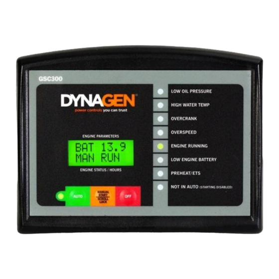
LED LAYOUT Front View of GSC300 Operating & Installation Manual for the GSC300 Engine Controller... -
Page 16: Led Indications
The engine has stalled, or the speed signal has been lost. Steady Engine Running LED Engine Controller is in running mode of operation. Flashing Engine Running LED Crank Rest period. Cranking will resume soon. Operating & Installation Manual for the GSC300 Engine Controller... - Page 17 Warm-Up To scroll through the parameters simply press the Auto button on the front panel of the GSC300. To scroll through the range of values for that parameter simply press the Manual Start button. To set the value into the controller’s memory, press the OFF button.
- Page 18 Numbering Of LED’s and Location of Mode Switch Programming Using the PC Interface The GSC300 can also be programmed using the PC interface. Detailed instructions on the PC interface are included with the GSC300 Configurator software. A sample interface screen is illustrated on the following page.
- Page 19 Sample Screen From PC Interface Operating & Installation Manual for the GSC300 Engine Controller...
-
Page 20: Suggested Action
>>> or <<< Warm-Up Feature appears Warm-Up Feature time setting does not Re-adjust Oil Bypass and/or Warm-Up longer then time setting. begin until the Oil Bypass Time has timing. expired. Operating & Installation Manual for the GSC300 Engine Controller... - Page 21 1. Controller Memory Clear Time The GSC300 needs 10 seconds for its memory to clear. When the power to the controller is turned off and then back on again without waiting a few seconds to clear the memory, a loss of speed will be indicated by the GSC300 because the controller remains in run mode and senses that the generator has stopped.
Need help?
Do you have a question about the GSC300 and is the answer not in the manual?
Questions and answers