Graco EM 390 Instructions-Parts List Manual
Hide thumbs
Also See for EM 390:
- Instructions and parts list (39 pages) ,
- Instructions for use manual (28 pages)
Table of Contents
Advertisement
Quick Links
STRUCTIONS-PARTS LIST
Never use 1,1,1-trichloroethane,methylene chloride, other halogenated hydrocarbon solvents or fluids containing
such solvents in this equipment. Such use could result in a serious chemical reaction, with the possibility of explo-
sion, which could cause death, serious bodily injury and/or substantial property damage.
Consult your fluid suppliers to ensure that the fluids being used are compatible with aluminum and zinc parts.
GRACO INC.
This manual contains IMPORTANT
WARNINGS and INSTRUCTIONS
READ AND RETAIN FOR REFERENCE
WARNING
P.O. BOX
COPYRIGHT 1985 GRACO INC.
Rev.
D
SUPERSEDES C
Advertisement
Table of Contents

Related Manuals for Graco EM 390


Summary of Contents for Graco EM 390
- Page 1 Such use could result in a serious chemical reaction, with the possibility of explo- sion, which could cause death, serious bodily injury and/or substantial property damage. Consult your fluid suppliers to ensure that the fluids being used are compatible with aluminum and zinc parts. P.O. BOX GRACO INC. COPYRIGHT 1985 GRACO INC.
- Page 2 HIGH PRESSURE SPRAY CAN CAUSE SERIOUS INJURY. PROFESSIONAL USE ONLY. OBSERVE ALL WARNINGS. Read and understand all instruction manuals before operating equipment. FLUID INJECTION HAZARD General Safety S p r a y S a f e t y D e v i c e s This equipment generates very high fluid pressure.
- Page 3 Hold a metal DO NOT expose Graco hose to temperatures above part of the gun firmly t o the side of a grounded metal pail and use the lowest possible fluid pressure during flushing.
- Page 4 La pulv6risation haute pression peut causer des blessures trhs graves. I'usage professionnel. Observer toutes les consignes de s6curit6. Bien lire bien comprendre tous Consignes g6n6rale.s de s k u r i t e Cet appareil produit un fluide B t r h haute pression. Le fiuide querait d'entrainer un mauvais fonctionnement et des blessures graves.
-
Page 5: Tuyaux Flexibles
generales de securite Pression C o n s i g n e s MAXIMUM Ce puivbrisateur peut produire un Toute utilisation anormale de I'appareil de pulvbrisation ou des TRAVAIL 172 S'assurer que tous les accessoires comme, par exemple, la mise sous une pression excessive, les modifications de pieces, I'utilisation de produits resister pression maximum de travail de ce pulvBrisateur. - Page 6 EL ROCIADO A ALTA PRESION PUEDE CAUSAR GRAVES LESIOMES. SOLO PARA US0 PROFESIONAL. RESPETE LOS AVISOS DE ADVERTENCIA. Lea y entienda todo manual de instrucciones antes de manejar el equipo. PELIGRO DE INYECCION DE FLUID0 Aparatos de seguridad de la pistola general p u l v e r i z a d o r a S e g u r i d a d...
- Page 7 PELIGRO POR MAL DEL EQUIP0 PELIGRO EXPLOSION flujo a aka velocidad del fluido al pasar por Seguridad general manguera crea electricidad estatica. Si todas las partes del Cualquier o 10s accesorios, tal equipo pulverizador no tienen buena tierra, pueden ocurrir como sobrepresurizaci6n.
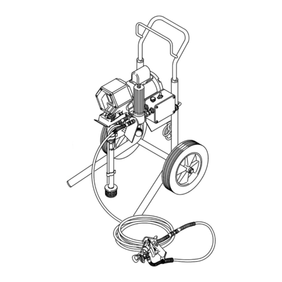
- Page 8 TERMS WARNING: Alerts user to avoid or correct conditions that could cause bodily injury. CAUTION: Alerts user to avoid or correct conditions that could cause damage to or destruction of equipment. NOTE: Identifies essential procedures or extra information. Basic E M 390 Components A.
- Page 9 4. Always use the main filter outlet. Never plug this outlet. 2. Fill Packing NutNVet-Cup (See Fig 2.) Fill the packing nut/wet-cup 1/3 full with Graco Throat Seal Liquid (TSL), supplied. 3. Check Electrical Service a. Be sure the' electrical service is 120 V, 60 HzAC, 15 Amp Iminimum) and that the outlet you use is properly grounded.
-
Page 10: Operation
OPERATION WARNING Pressure Relief Procedure To reduce the risk of serious bodily injury, in- cluding injection; splashing in the eyes; injury from moving parts or electric shock, always follow this procedure whenever you shut the sprayer, when checking or servicing any part of the spray system, when installing, cleaning or changing spray tips, and whenever you stop spraying. -
Page 11: Maintenance
Cleaning Clogged Tip W A R N I N G To reduce the risk of serious bodily injury from in- jection, use extreme caution when cleaning or changing spray tips. If the spray tip clogs while spraying, engage the gun safety latch immediate- ly, then follow the procedure in Steps 4a-4e. -
Page 12: Flushing Guidelines
FLUSHING GUIDELINES When t o Flush Storage. with motor oil which was left in to protect pump Water-base flush with watar, then mineral parts. spirits and leave the pump, hose and gun filled with Before using water-base paint, flush with mineral soirits. -
Page 13: Application Methods
APPLICATION METHODS Always hold the gun perpendicular to the surface and The best way to control the rate of coverage is with the to 14 in. (300-356 keep the gun at an even gun tip size. A small tip orifice applies less paint and a the surface you are spraying. -
Page 14: Troubleshooting Chart
SERVICE WARNING Relief Procedure Pressure To reduce the risk of serious bodily injury, including fluid injection; splashing in the eyes or on the skin; injury from moving parts or electric shock, always follow this procedure whenever you shut off the sprayer, when checking or servicing any pan of the spray'system, when installing, cleaning or changing spray tips, and whenever you stop spraying. - Page 15 PROBLEM CAUSE SOLUTION Excessive surge spray gun Spray tip or filter plugged Remove and clean Spray tip too big or worn Change spray tip. Paint too viscous Thin Use minimum 50h Wrong m a hose (15.2 nylon hose (wire braid hose unaccep- Pressure setting too low Increase Spray tip too big or worn...
- Page 16 REMOVING and REPLACING DISPLACEMENT P U M P (See Fig 14) To reduce the risk of serious bodily injury, in- cluding fluid injection; splashing in the eyes or on the skin; injury from moving parts or electric NOTE: The displacement pump repair instructions are in manual 307-793, supplied.
- Page 17 REMOVING and REPLACING ELECTRIC MOTOR WARMING Unscrew the nuts on both ends of the conduit (1) from the connectors. See Fig 16. Remove the screws (7). nuts and lockwashers (4). See Fig 15. Remove the motor from the frame while carefully guiding the wires through the connector in the control box.
- Page 18 REMOVING and REPLACING CONNECTING and BEARING (See Fig 17) reduce the risk of serious bodily injury, in- cluding fluid injection; splashing in the eyas or on the skin; injury from moving parts or electric Pressure Relief Pro- shock, always follow the cedure Warning on page before continuing.
- Page 19 REMOVING REPLACING DRIVE ASSEMBLY (See Fig 18) Clean and inspect the gear for wear or damage. Replace if necessary. To remove, drive out the pin (271 and pull the gear the motor shaft (C). Apply molybdenum disulfide spray lubricant to the gear, allow to dry, then apply industrial, heavy-duty, extreme- pressure, lithium-soap grease.
- Page 20 REMOVING REPLACING PRESSURE CONTROL Remove the nut (115) and washer (116) from the adapter (118) holding the filter to the mounting bracket. See Fig 20. Hold the nut (H) at the pressure control with a wrench and unscrew the swivel union from the nipple (313).
-
Page 21: Circuit Board Removal And Replacement
CIRCUIT BOARD REMOVAL AND REPLACEMENT ..Fig 24 If only the circuit board ( 2 3 ) needs to be replaced in the Position the new card at the control and the front Pressure control. remove the screws tors are at the top. -
Page 22: Control Calibration
PRESSURE CONTROL CALIBRATION (See Fig USE EXTREME CAUTION WHEN PERFORMING THIS CALIBRATION PROCEDURE to reduce the risk oi an injection injury or other serious bodily injury which can result from component rupture, electric shock, fire, ex. plosion, or moving parts. 1172 This procedure sets the sprayer to bar) -
Page 23: Parts List
TOGGLE, switch below. 2. Check the parts list to identify the correct part number; do not use the ret. no. when ordsrlng. 3. Order all parts from your nearest Graco distributor. 307-724... -
Page 24: Parts Drawing
PARTS LIST Model 231401 Baelc Sprayer, Model 231-390 Complete Sprayer w/Flex Gun items 1 to 119 Includes Includes items 1 119, PART DESCRIPTION Model 231418 Complete Sprayer w/Contractor Gun items 1 to 119, 201 to 205 Includes REF PART DESCRIPTION 100-214 215132 GUN, flex... - Page 25 PARTS DRAWING ..Includes ..items 119s to ..Ref No. 23 Eiectrlc Motor Assembly includes items . . . Ref No. 66 Drive Aaaembiy ..Includes items to !Sf...
- Page 26 Model 220-726 Basic Sprayer, Low Profile Cart, Model 231-051 Complete Sprayer wlth Flex Gun Includes items 1 to 126, 200 to 204 Series A Includes items REF PART DESCRIPTION REF PART DESCRIPTION NO. NO. GUN, flex, airless: sae 307-833 for 210541 HOSE, spray, cpld 1/4 npsm(fbet s w i v e l : CONDUIT.
- Page 27 PARTS DRAWING Model 231-061 Complete Sprayer with Flex Gun items 1 to 126, 200 to 204 Includes Model 1 to 126 Includes items No. 23 Electric Motor Assembly . .. Includes items ... .., .
-
Page 28: Technical Data
Sal e by an authorized Graco distributor to the original purchaser for use. As purchaser's sole remedy for breach of this warranty. Graco will. for a period of twelve months from the date of sale, repair or replace any part of the equipment proven defective. This warranty applies only when the equipment is installed.
Need help?
Do you have a question about the EM 390 and is the answer not in the manual?
Questions and answers