Knight 80 Service Manual
Hide thumbs
Also See for 80:
- Installation & operation manual (72 pages) ,
- Installation & operation manual (34 pages)
Table of Contents
Advertisement
Service Manual
Models: 80 - 500
This manual must only be
WARNING
used by a qualified heating
installer / service technician.
Read
all
instructions,
including this manual and the
Knight Boiler Installation and
Operation Manual, before
installing. Perform steps in
the order given. Failure to
comply could result in severe
personal injury, death, or
substantial property damage.
Save this manual for future reference.
Advertisement
Table of Contents
Troubleshooting

Subscribe to Our Youtube Channel
Related Manuals for Knight 80


Summary of Contents for Knight 80
- Page 1 Service Manual Models: 80 - 500 This manual must only be WARNING used by a qualified heating installer / service technician. Read instructions, including this manual and the Knight Boiler Installation and Operation Manual, before installing. Perform steps in the order given. Failure to...
-
Page 2: Table Of Contents
Service Manual Contents Contents ............2 Hazard definitions . -
Page 3: Please Read Before Proceeding
Please read before proceeding Installer – Read all instructions, When calling or writing about the boiler – WARNING NOTICE including this manual and the Knight Please have the boiler model and serial Boiler Installation Operation number from the boiler rating plate. - Page 4 Service Manual Please read before proceeding When servicing boiler – • To avoid electric shock, disconnect electrical supply before performing maintenance. • To avoid severe burns, allow boiler to cool before performing maintenance. Boiler operation – • Do not block flow of combustion or ventilation air to the boiler.
-
Page 5: What Is In This Manual
• Address reported problems • Typical system components • Inspect boiler area and boiler interior • Clean condensate trap The Knight boiler display • Check all piping for leaks • Display panel readout, buttons and their functions • Check air openings •... -
Page 6: Service
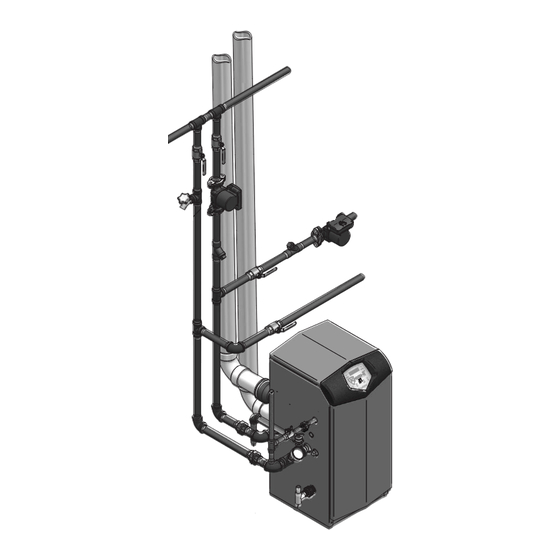
Near boiler piping This piping reference is included to specify the Near Boiler Piping specific to the Knight boiler. This piping scheme is important for proper operation of the SMART SYSTEM control. See the Knight Boiler Installation and Operation Manual for more... - Page 7 Service Manual Service Service (continued) The Knight boiler display...
- Page 8 Service Manual Service Service Control inputs...
- Page 9 Service Manual Service Service (continued) Control outputs...
-
Page 10: General Operation
How the boiler operates Access modes User The Knight boiler uses an advanced stainless steel heat exchanger and an electronic control module that allows fully The user can adjust space heating set point using the UP and condensing operation. The blower pulls in gas and air and DOWN buttons at any time during normal operation. -
Page 11: Sequence Of Operation
Service Manual Service Service (continued) Sequence of operation Table 1 Sequence of operation - space heating and DHW O O P P E E R R A A T T I I O O N N D D I I S S P P L L A A Y Y BLR: Standby 1. - Page 12 Service Manual Service Service Sequence of operation (continued) Table 1 (continued from previous page) Sequence of operation - space heating and DHW O O P P E E R R A A T T I I O O N N D D I I S S P P L L A A Y Y 8.
- Page 13 Service Manual Service Service (continued) Display panel menu access Table 2 Use this procedure to access menus from the display panel...
-
Page 14: Display Panel Parameter Access
Service Manual Service Service Display panel parameter access Table 3 This is a typical example of accessing a parameter, shown for parameter I2, boiler pump delay... -
Page 15: Parameter Table
Service Manual Service Service (continued) Parameter table Table 4 This table lists SMART SYSTEM control module parameters and where to access them U U S S E E R R A A C C C C E E S S S S I I N N S S T T A A L L L L E E R R A A C C C C E E S S S S S S E E E E M M E E N N U U... - Page 16 Service Manual Service Service Parameter table (continued) Table 4 (continued from previous page) This table lists SMART SYSTEM control module parameters and where to access them U U S S E E R R A A C C C C E E S S S S I I N N S S T T A A L L L L E E R R A A C C C C E E S S S S S S E E E E M M E E N N U U...
-
Page 17: Viewable And Changeable Control Parameters
A7. Each day of the week (Sunday through Saturday) will have an on and The control will display “Knight Boiler” as the model number off time. because the same control is used on several models. This will be displayed when parameter A1 has been accessed. - Page 18 Service Manual Service Service E: DHW settings SH Differential The SH differential sets how many degrees below the turn off DHW boiler set point temperature the temperature has to go before the boiler will turn on. This parameter can only be changed by the installer When a DHW call for heat becomes active, the control will by accessing parameter B5.
- Page 19 SH demands (DHW demands will still be active). This parameter can be changed by the user or the installer by accessing parameter F5. The temperature range of this parameter is 0°F to 120°F. The default value is 80°F.
- Page 20 When ramp delay is active, additional parameters for ramp delay operation will have to be adjusted. These can only be accessed by the optional PC software. See the Knight Boiler Smart System PC Program Instructions Manual for additional ramp delay parameter information.
- Page 21 These can only be accessed by the cascade set point. Therefore, this parameter can be used to optional PC software. See the Knight Boiler Smart System PC limit the outlet temperatures of all the boilers in a Cascade.
- Page 22 Service Manual Service Service Cascade offset Service notification running hours When the boiler control determines that a scheduled service is This parameter determines how much the temperature must due based on the hours of actual operation, the boiler display go above set point before the lead boiler will turn off. This will alternate the standard boiler display text with the message parameter can be adjusted by the installer by accessing SERVICE DUE every 5 seconds.
-
Page 23: Maintenance
Service Manual Maintenance Maintenance and annual startup Table 5 Service and Maintenance Schedules Owner maintenance Service technician (see the Knight User’s Information Manual for (see the following pages for instructions) instructions) • Check boiler area General: • Address reported problems •... -
Page 24: Address Reported Problems
2. Verify that air intake area is free of any of the contaminants listed in Section 1 of the Knight Boiler Installation and Operation Manual. If any of these are present in the boiler intake air vicinity, they must be removed. -
Page 25: Check Expansion Tank
Tanks may be open, closed or diaphragm or bladder type. disposal. Otherwise severe personal injury See Section 6 - Hydronic Piping of the Knight Boiler may result. If no water flows, valve is Installation and Operation Manual for suggested best inoperative. -
Page 26: Check Control Settings
Perform start-up and checks 1. Start boiler and perform checks and tests specified in Section 10 - Start-up of the Knight Boiler Installation and Operation Manual. 2. Verify cold fill pressure is correct and that operating pressure does not go too high. -
Page 27: Check Flame Signal
Oiled bearing circulators 1. Shut down boiler: • Follow the “To Turn Off Gas to Appliance” instructions 1. The circulator shipped with the Knight boiler is water- for the boiler in the Knight Boiler Installation and lubricated. No oiling is required. -
Page 28: Troubleshooting
7. Install control module cover and top access cover after fuse inspection. 8. Restore power to the boiler at the external line switch and verify boiler operation (Section 10 - Start-up in the Knight Boiler Installation and Operation Manual) after completing boiler service. -
Page 29: Troubleshooting Chart - No Display
Service Manual Troubleshooting (continued) Table 6 Troubleshooting Chart - No Display F F A A U U L L T T C C A A U U S S E E C C O O R R R R E E C C T T I I V V E E A A C C T T I I O O N N - No 120 vac supplied to unit. - Page 30 Service Manual Troubleshooting Checking temperature sensors The boiler temperature sensors (inlet water, outlet water, system water, flue, and outdoor air) are all resistance type devices. The following tables show the correct values for the sensors at various temperatures. Use an ohmmeter to read the resistance of the sensor at a known temperature.
-
Page 31: Troubleshooting Chart - Noisy System
C C O O R R R R E E C C T T I I V V E E A A C C T T I I O O N N - Supply gas problem. Natural gas pressures • Refer to Section 7 - Gas Connections of the Knight should be between 4 inches w.c. and Boiler Installation and Operation Manual for detailed 10.5 inches w.c. -
Page 32: Troubleshooting Chart - Fault Messages
8 - 13 inches w.c. reset once the condition has been corrected. • Refer to Section 7 - Gas Connections of the Knight Press the RESET button Boiler Installation and Operation Manual for detailed on the SMART SYSTEM information concerning the gas supply. - Page 33 4 - 10.5 inches w.c. and LP gas pressures should be between 8 - 13 inches w.c. Refer to Section 7 - Gas Connections of the Knight Boiler Installation and Operation Manual for detailed information concerning the gas supply.
- Page 34 4 - 10.5 inches w.c. and LP gas pressures should be between 8 - 13 inches w.c. Refer to Section 7 - Gas Connections of the Knight Boiler Installation and Operation Manual for detailed information concerning the gas supply.
- Page 35 Refer to Section 6 - Hydronic Piping of the Knight Boiler Installation and Operation Manual for the proper piping methods for the Knight boiler. • Check 120 vac to boiler pump motor on a call for heat. If voltage is not present, check wiring back to the main control board.
- Page 36 • Vent/air intake lengths exceed the maximum allowed is being called for. lengths. Refer to Section 3 - General Venting of the Knight Boiler Installation and Operation Manual for proper lengths. Fan High • Check for obstruction or blockage in the vent/air intake pipes or at terminations.
- Page 37 Refer to Section 6 - Hydronic Piping of the Knight Boiler Installation and Operation Manual for the proper piping methods for the Knight boiler. • Check for 120 vac to the boiler pump motor on a call for heat. If voltage is not present, check the wiring back to the main control board.
- Page 38 • Verify that the boiler pump is set to the proper speed maximum outlet water temperature. or that the boiler pump is the proper size. Reference Section 6 - Hydronic Piping of the Knight Boiler Installation and Operation Manual for boiler pump Temp O/Shoot specifications.
- Page 39 Refer to Section 6 - Hydronic Piping of the Knight Boiler Installation Operation Manual for the proper piping methods for the Knight boiler. Service Blk • Check 120 vac to the boiler pump motor on a call for heat. If voltage is not present, check the wiring back to the main control board.
-
Page 40: Combustion Analysis Procedure
C C O O R R R R E E C C T T I I V V E E A A C C T T I I O O N N • Refer to Section 3 - General Venting of the Knight Boiler Installation and Operation Manual for the proper venting and air intake methods for the Knight boiler. -
Page 41: Gas Valve Adjustment Procedure
Table 10 on page 40 or replace the gas Figure 6 Gas Valve Adjustment: Models 80 - 285 valve. Figure 7 Gas Valve Adjustment: Model 500... -
Page 42: Notes Page
Service Manual Notes... - Page 43 Service Manual Notes...
- Page 44 KB-SER-03 CP-3M-3/07...
Need help?
Do you have a question about the 80 and is the answer not in the manual?
Questions and answers