Advertisement
Table of Contents
- 1 Quick Start
- 2 Important Safety Information
- 3 Features
- 4 Replacing Existing Thermostat
- 5 Install Thermostat
- 6 To Test Thermostat
- 7 Setting/Changing Setpoint Temperature
- 8 Changing Temperature Differential
- 9 Operation
- 10 Led Indicators
- 11 Troubleshooting
- 12 Changing Fahrenheit (F) to Celsius (C)
- 13 Wiring Diagrams
- 14 Five Year Limited Warranty
- Download this manual
I N T E G R A T E D C O M F O R T S O L U T I O N S
110-733
110-733C
IMPORTANT SAFETY INFORMATION
WARNING:
• Always turn off power at the main power source by unscrewing
fuse or switching circuit breaker to the off position before installing,
removing, cleaning or servicing thermostat.
• Read all of the information in this manual before installing or pro-
gramming this thermostat
• This is a 24V AC low-voltage thermostat. Do not install on voltages
higher than 30V AC.
• All wiring must conform to local and national building and electrical
codes and ordinances.
• Do not short (jumper) across terminals on the gas valve or at the
system control to test installation. This will damage the thermostat
and void the warranty
9520
®
™
1
DIGITAL
NON-PROGRAMMABLE
THERMOSTAT
H
HEAT PUMP
2 Heat / 2 Cool
User's Manual
Quick Start
Installation
Advertisement
Table of Contents

Related Manuals for Robertshaw 9520


Summary of Contents for Robertshaw 9520
-
Page 1: Quick Start
9520 DIGITAL NON-PROGRAMMABLE THERMOSTAT ® ™ I N T E G R A T E D C O M F O R T S O L U T I O N S HEAT PUMP 2 Heat / 2 Cool User’s Manual... -
Page 2: Features
Features • Multi Stage heat and cooling control • Zone system compatible as a master thermostat • Multi-Colored LED indicators for system status • Low battery indicator. • Fahrenheit/Celsius display option. • Adjustable from 45°F (4°C) to 90°F (32°C). • Accuracy within ± 1 degree. •... -
Page 3: Install Thermostat
4. After labeling wires, remove wires from terminals. 5. Remove existing thermostat base from wall. 6. Refer to the following section for instructions on how to install thermostat. Figure 1 Installing Model 9520 Thermostat NOTE: F , 4-5 OR NEW INSTALLATIONS MOUNT THERMOSTAT ON INSIDE WALL... - Page 4 5. Place thermostat against the wall at desired location. Make sure wires will feed through opening on base of thermostat. 6. Mark placement of mounting holes. See Fig. 3. Set base aside. Mounting Holes Batteries NOT Required. figure 3 7. Drill the marked holes using a 3/16" drill bit. NOTE: Enclosed plastic anchors do not require a drilled hole for drywall.
- Page 5 11. Connect wires to terminal strip. Refer to wiring diagrams on other side of this sheet. Make sure wire connections are secure. 12. Put the °F/°C switch to either °F for Fahrenheit display or °C for Celsius display readout. F/ C Switch Batteries NOT Required.
-
Page 6: To Test Thermostat
To Test Thermostat WARNING: DO NOT SHORT (JUMPER) ACROSS TERMINALS OF GAS VALVE OR SYSTEM CONTROL TO TEST OPERATION. THIS WILL DAMAGE THE THERMOSTAT AND VOID YOUR WARRANTY. CAUTION: D 50(F (10(C). O NOT SWITCH SYSTEM TO COOL IF THE TEMPERATURE IS BELOW HIS CAN DAMAGE THE AIR CONDITIONING SYSTEM AND CAUSE PERSONAL INJURY 1. -
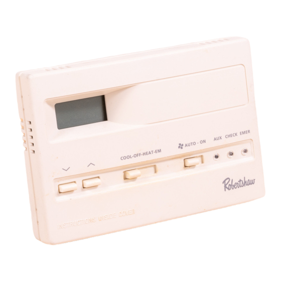
Page 7: Setting/Changing Setpoint Temperature
Operation Setting or Changing the Setpoint Temperature 1. Press either the button. The display will show the current temperature setpoint. COOL-OFF-HEAT-EM AUTO - ON AUX CHECK EMER 2. Press either the button to adjust the temperature setting either up or down. The display will return to the room temperature display five seconds after the last input and the new setpoint will be saved. -
Page 8: Led Indicators
Changing Fahrenheit (F) to Celsius (C) The thermostat is preset to display the temperature in degrees Fahrenheit. You may change the display readout to Celsius if desired. 1. Move the manual switch marked “F” (Fahrenheit) and “C” (Celsius) located at the top center of the circuit board to the desired setting. (see page 5) 2. - Page 9 If problems with thermostat cannot be solved, call: Technical Support: (800) 445-8299 Monday-Friday 7:30-5:30 CST For warranty returns, send thermostat, shipping prepaid to: Uni-Line North America Warranty Claims Department 515 S. Promenade Corona, CA 91719...
-
Page 10: Wiring Diagrams
Wiring Diagrams The following is just a sample of the most common types of HVAC systems. Refer to your systems installation manual for wiring information. ROBERT SHAW HEAT PUMP THERMOSTAT CONVERSION TO CARRIER SPLIT SYSTEM CONDENSORS AND HEAT PUMP SYSTEMS ROBERT SHAW HEAT PUMP THERMOSTAT 24 VAC, RETURN COMPRESSOR CONTACTOR... - Page 11 ROBERT SHAW HEAT PUMP THERMOSTAT CONVERSION TO COMFORTMAKER CYC SERIES HEAT PUMP SYSTEMS NOTE 1: E AND W2 TERMINALS JUMPERED AT THERMOSTAT ROBERT SHAW HEAT PUMP THERMOSTAT NOTE 2: W2 TERMINAL ON COMFORTMAKER PCB CAPPED NOTE 3: X TERMINAL ON COMFORTMAKER PCB CAPPED 24 VAC, RETURN COMPRESSOR CONTACTOR...
- Page 12 ROBERT SHAW HEAT PUMP THERMOSTAT CONVERSION TO PAYNE RELIANT AND ENDURA MODEL HEAT PUMP SYSTEMS NOTE 1: W3 TERMINAL ON ROBERT SHAW HEAT PUMP THERMOSTAT PAYNE PCB CAPPED 24 VAC, RETURN COMPRESSOR CONTACTOR REVERSING VALVE [COOLING MODE] FAN CONTACTOR CIRCUIT EMERGENCY HEATING CIRCUIT 2ND.
- Page 13 ROBERT SHAW HEAT PUMP THERMOSTAT CONVERSION TO WEATHERTRON HEAT PUMPS NOTE 1: E AND W2 TERMINALS JUMPERED AT THERMOSTAT ROBERT SHAW HEAT PUMP THERMOSTAT NOTE 2: X2 TERMINAL CAPPED AT WEATHERTRON PCB NOTE 3: T TERMINAL CAPPED AT WEATHERTRON PCB 24 VAC, RETURN COMPRESSOR CONTACTOR REVERSING VALVE [COOLING MODE]...
- Page 14 ROBERT SHAW HEAT PUMP THERMOSTAT CONVERSION TO LENNOX CB19 HEAT PUMP SYSTEMS ROBERT SHAW HEAT PUMP THERMOSTAT 24 VAC, RETURN COMPRESSOR CONTACTOR REVERSING VALVE [COOLING MODE] FAN CONTACTOR CIRCUIT EMERGENCY HEATING CIRCUIT 2ND. STAGE HEATING CIRCUIT SYSTEM MONITOR LED 24 VAC, COMMON THE LOW VOLTAGE TERMINAL DESIGNATIONS AND THEIR DESCRIPTION AND/OR FUNCTION ARE USED ON ALL SPLIT SYSTEM CONDENSORS AND HEAT PUMPS ROBERT SHAW HEAT PUMP THERMOSTAT CONVERSION TO LENNOX...
- Page 15 ROBERT SHAW HEAT PUMP THERMOSTAT CONVERSION TO LENNOX HP21 WITH CB21 PCB HEAT PUMP SYSTEMS ROBERT SHAW HEAT PUMP THERMOSTAT 24 VAC, RETURN R-VR COMPRESSOR CONTACTOR REVERSING VALVE [COOLING MODE] FAN CONTACTOR CIRCUIT EMERGENCY HEATING CIRCUIT 2ND. STAGE HEATING CIRCUIT 24 VAC, COMMON THE LOW VOLTAGE TERMINAL DESIGNATIONS AND THEIR DESCRIPTION AND/OR FUNCTION ARE USED ON ALL SPLIT SYSTEM CONDENSORS AND HEAT PUMPS...
-
Page 16: Five Year Limited Warranty
Five Year Limited Warranty Maple Chase Company warrants to the original contractor installer or to the original consumer user, each new Maple Chase thermostat to be free from defects in materials and workmanship under normal use and service for a period of five (5) years from date of purchase. This warranty and our liability does not apply to batteries or the merchandise that has been damaged, caused by misuse, neglect, mishandling, alterations, improper installation, or use in a way other than in accordance with...
Need help?
Do you have a question about the 9520 and is the answer not in the manual?
Questions and answers