Subscribe to Our Youtube Channel
Summary of Contents for BRAX X 1400
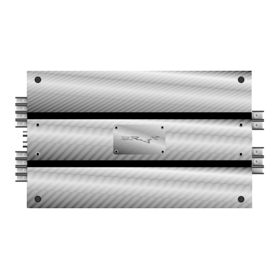
- Page 1 INNOVATIVE AUDIO PERFORMANCES MADE IN GERMANY X 1400 X 2400 4-Channel Amplifier Instruction Manual...
-
Page 2: Table Of Contents
Introduction and Contents ....Page 2 Installing the BRAX Amplifiers ....Page 3 Congratulations on your purchase of this high-quality Connection of the BRAX Amplifiers . -
Page 3: Installing The Brax Amplifiers
Install your amplifier at a dry location in the car where installed by an authorized BRAX dealer. Installation by a there is sufficient air circulation to ensure adequate cooling qualified and accredited technician will qualify you for our of the equipment. -
Page 4: Connection Of The Brax Amplifiers
Installation and Connection of BRAX Amplifiers X 1400 and X 2400 The above amplifier models may only be installed in In order to avoid cross-talk distortion, audio cables should motor vehicles which have a 12-volt negative terminal never be laid together with electrical leads (with the excep- connected to the chassis ground. -
Page 5: Connection Of The Power Supply
20 cm from the positive terminal of the amplifier and equipped with the original BRAX fuse provided. The fuse ratings are: for amplifier X 1400 = 60 A, for amplifier X 2400 = 100 A. Failure to comply nullifies the warranty. -
Page 6: Connection Of The Speaker Cables
Connection of the Speaker Cables Important! Never connect the speaker cables to the vehicle chassis. Fig. 5: 2-Channel Mode This can destroy your amplifier. Ensure that all the speaker Mono Input Mono Input systems are connected in-phase, i.e. plus to plus and minus Front right Rear right to minus. -
Page 7: Circuit Control Cards Ccc
Circuit Control Card from the list ordering, the amplifier is supplied as standard with CCC 1. (in this case CCC 5) and insert the card in your BRAX CCC 1 is plugged in at socket position 3 which means that... -
Page 8: Circuit Control Cards Data Sheet
List of Circuit Control Cards (CCC) Card No. Type Frequency CCC Position No. in Hz CCC 1 subsonic 18 dB/Oct. full range CCC 2 highpass 18 dB/Oct. lowpass 18 dB/Oct. full range CCC 3 highpass 18 dB/Oct. lowpass 18 dB/Oct. full range CCC 4 highpass 18 dB/Oct. -
Page 9: What If?/Troubleshooting
Parasitics in the cinch cable. Check the connections (screen/shield). engine. Parasitics in the power supply Replace the cable with screened cabling. BRAX POWER TRAX cable. Consult your dealer. Feedback interference from the chas- Select an optimum central ground sis to the control unit (radio/tuner). -
Page 10: Equipment Features And Control Elements
Use the enclosed set-screw for this action. The level controllers enable the input sensitivity of the BRAX amplifiers to be adapted to the output voltage of the connected control unit (radio/tuner). These controllers are not volume controls. Optimum setting of the level control-... - Page 11 Equipment Features and Control Elements...
-
Page 12: Technical Specifications
Technical Specifications X 1400 X 2400 Continuous power rating at 4 Ohm per channel ..4 x 50 Watts ....4 x 100 Watts Continuous power rating at 2 Ohm per channel .


Need help?
Do you have a question about the X 1400 and is the answer not in the manual?
Questions and answers