Table of Contents
Advertisement
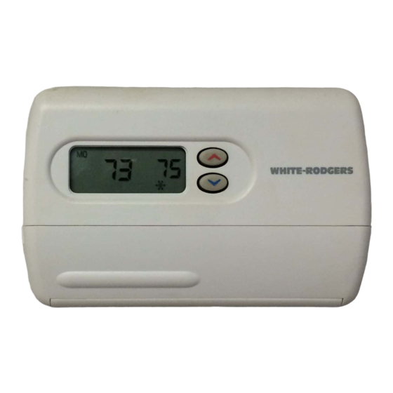
Installation Instructions for
Heating & Cooling
Digital Model 850
5/1/1 Day Programmable
Thermostat
YOUR THERMOSTAT REPLACES
Description
Standard Heat & Cooling Systems - 4 or 5 wires
Standard Heat Only Systems
Millivolt Heat Only Systems - Floor or Wall Furnaces
Standard Central Air Conditioning
Gas or Oil Heat
Electric Furnace
Hydronic (Hot Water) Zone Heat - 2 Wires
Hydronic (Hot Water) Zone Heat - 3 Wires
Heat Pump (No Aux or Emergency Heat)
Heat Pump (with Aux or Emergency Heat)
Baseboard Electric Heating or Line Voltage (120 or 240 volt)
2
THERMOSTAT DETAILS
Mounting
Electric/Gas
holes
switch
Figure 1. Thermostat base
1
850
Yes
Yes
Yes
Yes
Yes
Yes
Yes
No
Yes
No
No
3
Screw anchors
Mounting
holes
White-Rodgers is a division
of Emerson Electric Co.
www.white-rodgers.com
CONTENTS
Preparations .................................................. 1
Thermostat Details ........................................ 1
Removing Old Thermostat ............................ 1
Mounting and Wiring ..................................... 2
Check Thermostat Operation ........................ 4
Specifications ................................................ 7
Troubleshooting ............................................ 7
PREPARATIONS
Assemble tools required as shown below.
FLAT BLADE SCREWDRIVER
HAND OR POWER
DRILL WITH 3/16 INCH
DRILL BIT, IF NEEDED
SPIRIT LEVEL OR PLUMB BOB AND LINE (OPTIONAL)
Failure to follow and read all instructions carefully
before installing or operating this control could cause
personal injury and/or property damage.
REMOVING OLD THERMOSTAT
CAUTION
!
To prevent electrical shock and/or equipment damage,
disconnect electrical power to the system at the main
fuse or circuit breaker until installation is complete.
Before removing wires from old thermostat's switching subbase,
label each wire with the terminal designation it was removed from.
1. Remove Old Thermostat: A standard heat/cool thermostat
consists of three basic parts:
a. The cover, which may be either a snap-on or hinge type.
b. The base, which is removed by loosening all captive screws.
c. The switching subbase, which is removed by unscrewing
the mounting screws that hold it on the wall or adaptor plate.
2. Shut off electricity at the main fuse box until installation is
complete. Ensure that electrical power is disconnected.
3. Remove the front cover of the old thermostat. With wires still
attached, remove wall plate from the wall. If the old thermostat
has a wall mounting plate, remove the thermostat and the wall
mounting plate as an assembly.
4. Identify each wire attached to the old thermostat using the
labels enclosed with the new thermostat.
5. Disconnect the wires from the old thermostat one at a time. DO
NOT LET WIRES FALL BACK INTO THE WALL.
6. Install new thermostat using the following procedures.
WIRE CUTTER/STRIPPER
PART NO. 37-6295B
Replaces 37-6295A
0514
Advertisement
Table of Contents
Troubleshooting

Related Manuals for White Rodgers 850


Summary of Contents for White Rodgers 850
-
Page 1: Table Of Contents
Thermostat Details ........1 Installation Instructions for Removing Old Thermostat ......1 Mounting and Wiring ........2 Heating & Cooling Check Thermostat Operation ......4 Digital Model 850 Specifications ..........7 Troubleshooting ..........7 5/1/1 Day Programmable Thermostat YOUR THERMOSTAT REPLACES... -
Page 2: Mounting And Wiring
REMOVING OLD THERMOSTAT CAUTION CONTINUED FROM FIRST PAGE Take care when securing and routing wires so they do ATTENTION! This product does not contain mercury. How- not short to adjacent terminals or rear of thermostat. ever, this product may replace a unit which contains mercury. Personal injury and/or property damage may occur. - Page 3 MOUNTING AND WIRING CONTINUED FROM SECOND PAGE THERMOSTAT C ‡ SYSTEM JUMPER Cooling Heating WIRE 24 VAC 120 VAC System Relay System THERMOSTAT C ‡ Neutral SYSTEM HEATING TRANSFORMER Heating Relay System 24 VAC 120 VAC 24 VAC 120 VAC NOTE Neutral Neutral...
-
Page 4: Check Thermostat Operation
CHECK THERMOSTAT OPERATION If at any time during testing your system does not operate properly, contact a qualified service person. Turn on power to the system. Fan Operation If your system does not have a G terminal connection, skip to Heating System. - Page 5 5) Select filter replacement run time - The thermostat will CHECK THERMOSTAT OPERATION display “FLTR” after a set time of operation. This is a reminder to change or clean your air filter. This time can be CONTINUED FROM FOURTH PAGE set from 0 to 1950 hours in 50 hour increments.
-
Page 6: Programming Your Thermostat
Set Current Time and Day CHECK THERMOSTAT OPERATION 1. Press TIME button once. The display will show the hour only. CONTINUED FROM FIFTH PAGE • HOLD TEMPERATURE — The thermostat can hold any EXAMPLE: temperature within its range for an indefinite period without reverting to the programmed temperature. -
Page 7: Specifications
1. Move SYSTEM switch to COOL position. PROGRAMMING YOUR THERMOSTAT 2. Follow the procedure for entering your heating program, using CONTINUED FROM SIXTH PAGE your selected cooling times and temperatures. 7. Repeat steps 3 through 5 for the 3rd and 4th heating program Check Your Programming periods. -
Page 8: Troubleshooting
Replace batteries and check heat/cool system Not Responding 2. Battery change required. for proper operation. If a voltage spike occurs use the Reset Operation listed below. The Emerson logo is a trademark and a service mark of Emerson Electric Co. www.white-rodgers.com...
Need help?
Do you have a question about the 850 and is the answer not in the manual?
Questions and answers