Table of Contents
Advertisement
Advertisement
Table of Contents

Related Manuals for Asus P3B-F


Summary of Contents for Asus P3B-F
- Page 1 ® P3B-F ® Pentium III / II / Celeron Motherboard USER’S MANUAL...
- Page 2 Product warranty or service will not be extended if: (1) the product is repaired, modified or altered, unless such repair, modification of alteration is authorized in writing by ASUS; or (2) the serial number of the product is defaced or missing.
-
Page 3: Asus Contact Information
ASUS COMPUTER GmbH (Europe) Marketing Address: Harkortstr. 25, 40880 Ratingen, BRD, Germany Fax: +49-2102-442066 Email: sales@asuscom.de (for marketing requests only) Technical Support Hotline: MB/Others: +49-2102-9599-0 Notebook: +49-2102-9599-10 Fax: +49-2102-9599-11 Support (Email): www.asuscom.de/de/support (for online support) WWW: www.asuscom.de FTP: ftp.asuscom.de/pub/ASUSCOM ASUS P3B-F User’s Manual... -
Page 4: Table Of Contents
1. INTRODUCTION ................7 1.1 How This Manual Is Organized ..........7 1.2 Item Checklist ................7 2. FEATURES ..................8 2.1 The ASUS P3B-F Motherboard ..........8 2.1.1 Specifications ..............8 2.1.2 Special Features ............. 10 2.1.3 Performance Features ............ 10 2.1.4 Intelligence .............. - Page 5 5.2 P3B-F Support CD ..............75 5.3 Intel LDCM Administrator Setup ..........77 5.4 Intel LDCM Client Setup ............78 5.5 Install ASUS PC Probe Vx.xx ..........80 5.6 Install ASUS Update Vx.xx ............81 5.7 Install PC-Cillin 98 Vx.xx ............82 5.8 Install ADOBE AcroBat Reader Vx.x ........
-
Page 6: Federal Communications Commission Statement
Radio Interference Regulations of the Canadian Department of Communications. This Class B digital apparatus complies with Canadian ICES-003. Cet appareil numérique de la classe B est conforme à la norme NMB-003 du Canada. ASUS P3B-F User’s Manual... -
Page 7: Introduction
(1) Support CD with drivers and utilities (1) This Motherboard User’s Manual ASUS IrDA-compliant infrared module (optional) ASUS S370-133 CPU card (optional) ASUS CIDB Chassis Intrusion Detection Module (optional) ASUS PCI-L101 Wake-On-LAN 10/100 ethernet card (optional) ASUS P3B-F User’s Manual... -
Page 8: Features
2. FEATURES 2.1 The ASUS P3B-F Motherboard The ASUS P3B-F is carefully designed for the demanding PC user who wants ad- vanced features processed by the fastest CPU. 2.1.1 Specifications • Latest Intel Processor Support: Intel Pentium III 100MHz FSB, Katmai core... - Page 9 Single Edge Processor Package (SEPP). • Wake-On-LAN Connector: Supports Wake-On-LAN activity through an op- tional ASUS PCI-L101 10/100 Fast Ethernet PCI card (see 7.1 PCI-L101 Fast Ethernet Card) or a similar ethernet card. • Wake-On-Ring Connector: Supports Wake-On-Ring activity through a PCI modem card which supports a WOR connector.
-
Page 10: Special Features
Concurrent PCI: Concurrent PCI allows multiple PCI transfers from PCI mas- ter busses to the memory and processor. • Double the IDE Transfer Speed: ASUS smart series motherboards with Intel chipsets improve IDE transfer rate using Bus Master UltraDMA/33 IDE which can handle data transfers up to 33MB/s. -
Page 11: Intelligence
• Chassis Intrusion Detection: Supports chassis-intrusion monitoring through the ASUS ASIC. A chassis intrusion event is kept in memory on battery power for more protection. ASUS P3B-F User’s Manual... -
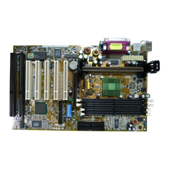
Page 12: P3B-F Motherboard Components
Supports Plug & Play, DMI, and Write Protection Network Features Wake-On-LAN Connector ............14 Wake-On-Ring Connector ............11 Hardware Monitoring System Voltage Monitoring (integrated in ASUS ASIC) ..6 3 Fan Power and Speed Monitoring Connectors Power ATX Power Supply Connector ..........1 Special Features Onboard Power LED .............. - Page 13 2. FEATURES P3B-F Motherboard Component Locations ASUS P3B-F User’s Manual...
-
Page 14: Hardware Setup
3. HARDWARE SETUP 3.1 P3B-F Motherboard Layout PWR_FAN TOP: ATXPWR JP20 Mouse (VIO) KBMS BOTTOM: Keyboard CPU_FAN TOP: USB 1 BOTTOM: USB 2 COM1 Intel 440BX AGPset COM2 JTPWR Accelerated Graphics Port CR2032 3V Lithium Cell (CMOS Power) PLED2 Switches... -
Page 15: Layout Contents
37 ATX / Soft-Off Switch Lead (2 pins) 21) RESET (PANEL) p. 37 Reset Switch Lead (2 pins) 22) ATXPWR p. 38 ATX Power Supply Connector (20 pins) 23) JTPWR p. 38 Thermal Sensor Connector ASUS P3B-F User’s Manual... -
Page 16: Hardware Setup Procedure
3. Hold components by the edges and try not to touch the IC chips, leads or connectors, or other components. 4. Place components on a grounded antistatic pad or on the bag that came with the component whenever the components are separated from the system. ASUS P3B-F User’s Manual... - Page 17 1 2 3 4 5 7 8 9 10 DRAM Freq. x1 DRAM Freq. x2/3 P3B-F AGP Bus Frequency Setting WARNING! AGP bus frequencies above 66MHz exceed the specifications for the AGP interface and are not guaranteed to be stable.
- Page 18 Voltage Regulator Output Selection (VID) is not needed for the Pentium III / II / Celeron processor because it sends VID signals directly to the onboard power controller. WARNING! Frequencies above 100MHz exceed the specifications for the onboard Intel Chipset and are not guaranteed to be stable. ASUS P3B-F User’s Manual...
- Page 19 Pentium II/Celeron 266MHz 4.0x 66MHz [OFF][OFF] [ON] [ON] [ON] [ON] [OFF] [ON] [ON] Pentium II 233MHz 3.5x 66MHz [OFF][OFF] [ON] [ON] [OFF][OFF] [ON] [ON] [ON] For updated processor settings, please visit ASUS’ web site (see ASUS CONTACT INFORMATION). ASUS P3B-F User’s Manual...
- Page 20 1 2 3 Jumper JumperFree P3B-F Jumper Mode Setting NOTE: In JumperFree mode, your system will start up at a bus speed of 66MHz (2.0x frequency multiplier is used for processors with unlocked multiplier) and automatically enter BIOS setup for you to select your processor internal speed after you have changed/reinstalled the processor or after a system hangup due to improper CPU settings (see 4.4 Advanced Menu).
-
Page 21: System Memory (Dimm)
If your DIMMs are not PC100-compliant, set the CPU bus frequency to 66MHz RAM to ensure system stability. • ASUS motherboards support SPD (Serial Presence Detect) DIMMs. This is the memory of choice for best performance vs. stability. •... -
Page 22: Memory Installation
88 Pins 60 Pins 20 Pins P3B-F 168-Pin DIMM Memory Sockets The DIMMs must be 3.3Volt unbuffered SDRAMs. To determine the DIMM type, check the notches on the DIMMs (see figure below). The notches on the DIMM will shift between left, center, or right to identify the type and also to prevent the wrong type from being inserted into the DIMM slot on the motherboard. -
Page 23: Central Processing Unit (Cpu)
SECC, or a Celeron™ processor packaged in a Single Edge Processor Pack- age (SEPP). An ASUS S370-133 CPU card can allow Socket 370 processors to be used on any ASUS motherboard with the Slot 1 connector (See 7.APPENDIX for instructions on using this card). -
Page 24: Attaching The Heatsink
SECC2 heatsink and fan except that the clamping design is different. WARNING! Make sure the heatsink is mounted tightly against the SECC2, SECC, or SEPP; otherwise, the CPU will overheat. You may install an auxiliary fan to provide adequate circulation across the processor’s passive heatsink. ASUS P3B-F User’s Manual... -
Page 25: Installing The Universal Retention Mechanism
URM to be installed improperly but will also damage the URM. 5. Push the four retainer pins completely down into the black fastener sleeves until the head of each pin is securely seated. ASUS P3B-F User’s Manual... -
Page 26: Installing The Processor
Lock hole CPU fan CPU fan cable to cable to fan fan connector connector 3. If your URM is of type A, make sure the locks are in the locked position as shown. Locked Position (push upward) ASUS P3B-F User’s Manual... -
Page 27: Removing The Processor
RPM and use the alert function with the Intel LANDesk Client Manager (LDCM) or the ASUS PC Probe software. SECC Heatsink & Fan SECC2 Heatsink & Fan NOTE: The SEPP heatsink and fan (for Intel Celeron processors) is similar to the SECC2 heatsink and fan except that the clamping design is different. - Page 28 4. There is no visible gap between the processor die and heatsink. The thermal interface material should be continuous with no through-holes or debris. Example of an incorrectly installed retention clip Example of a correctly installed retention clip ASUS P3B-F User’s Manual...
-
Page 29: Expansion Cards
PCI groups that will make the system unstable or cards inoperable. Interrupt Request Table INT-A INT-B INT-C INT-D PCI slot 1 shared PCI slot 2 shared PCI slot 3 shared PCI slot 4 shared PCI slot 5 shared PCI slot 6 shared shared ---- shared ASUS P3B-F User’s Manual... -
Page 30: Standard Interrupt Assignments
Computer to see all the interrupts and addresses for your system. Make sure that no two devices use the same IRQ or your computer will experience problems when those two devices are in use at the same time. ASUS P3B-F User’s Manual... -
Page 31: Assigning Dma Channels For Isa Cards
DMAs you want to reserve). 3.7.4 Accelerated Graphics Port (AGP) This motherboard provides an accelerated graphics port (AGP) slot to support a new generation of graphics cards with ultra-high memory bandwidth, such as an ASUS 3D Hardware Accelerator. WARNING! Make sure that you unplug your power supply when adding or removing an AGP card or other system components. -
Page 32: External Connectors
This connection is for a standard keyboard using an PS/2 plug (mini DIN). This connector will not allow standard AT size (large DIN) keyboard plugs. You may use a DIN to mini DIN adapter on standard AT keyboards. PS/2 Keyboard (6-pin Female) ASUS P3B-F User’s Manual... - Page 33 (Pin 5 is removed to prevent inserting in the wrong orienta- tion when using ribbon cables with pin 5 plugged). NOTE: Orient the red stripe to Pin 1 Floppy Drive Connector Pin 1 P3B-F Floppy Disk Drive Connector ASUS P3B-F User’s Manual...
- Page 34 You may install one operating system on an IDE drive and another on a SCSI drive and select the boot disk through Boot Sequence in 4.6 Boot Menu. NOTE: Orient the red stripe to PIN 1 PIN 1 P3B-F IDE Connectors ASUS P3B-F User’s Manual...
- Page 35 NOTE: The “Rotation” signal is to be used only by a specially designed fan with rotation signal. The Rotations per Minute (RPM) can be monitored using ASUS PC Probe Utility or Intel LDCM Utility (see 6. Software Reference).
- Page 36 For the infrared feature to be available, you must connect the optional Infrared (IrDA) module to the motherboard. P3B-F Infrared Module Connector 11) SMBus Connector (5-1 pin SMB) This connector allows you to connect SMBus devices. SMBus devices commu- nicate by means of the SMBus with an SMBus host and/or other SMBus de- vices.
- Page 37 12) Wake-On-LAN Connector (3-pin WOL_CON) The WOL_CON connector powers up the system when a wake-up packet or signal is received from the network through the ASUS PCI-L101 LAN card. IMPORTANT: This feature requires that Wake-On-LAN is set to Enabled (see 4.5.1 Power Up Control) and that your system has an ATX power supply with at...
- Page 38 The sensor is triggered when a high level signal is sent to the Chassis Signal lead, which occurs when a panel switch or light detec- tor is triggered. This function requires the optional ASUS CIDB chassis intru- sion module to be installed (see 7. APPENDIX).
- Page 39 Requires an ATX power supply. Speaker Keyboard Lock Connector Power LED Message LED Reset SW ATX Power Switch* SMI Lead P3B-F System Panel Connections ASUS P3B-F User’s Manual...
- Page 40 +5.0 Volts +12.0 Volts +5.0 Volts ATXPWR P3B-F ATX Power Connector IMPORTANT: Make sure that your ATX power supply can supply at least 10mA on the 5-volt standby lead (5VSB). You may experience difficulty in powering on your system if your power supply cannot support the load. For Wake-On- LAN, keyboard wake up, and suspend-to-RAM support, your ATX power sup- ply must supply at least 720mA +5VSB.
-
Page 41: Starting Up The First Time
No DRAM installed or detected One long beep followed by Video card not found or video card three short beeps memory bad High frequency beeps when CPU overheated system is working System running at a lower frequency ASUS P3B-F User’s Manual... -
Page 42: Bios Setup
4. In DOS mode, type A:\AFLASH <Enter> to run AFLASH. IMPORTANT! If “unknown” is displayed after Flash Memory:, the memory chip is either not programmable or is not supported by the ACPI BIOS and there- fore, cannot be programmed by the Flash Memory Writer utility. ASUS P3B-F User’s Manual... -
Page 43: Updating Bios Procedures (Only When Necessary)
<Enter>. 4.1.2 Updating BIOS Procedures (only when necessary) 1. Download an updated ASUS BIOS file from the Internet (WWW or FTP) (see ASUS CONTACT INFORMATION on page 3 for details) and save to the disk you created earlier. 2. Boot from the disk you created earlier. - Page 44 BIOS file you saved to disk above. If the Flash Memory Writer utility was not able to successfully update a complete BIOS file, your system may not be able to boot up. If this happens, your system will need servicing. ASUS P3B-F User’s Manual...
-
Page 45: Bios Setup Program
POST. NOTE: Because the BIOS software is constantly being updated, the following BIOS screens and descriptions are for reference purposes only and may not re- flect your BIOS screens exactly. ASUS P3B-F User’s Manual... -
Page 46: Bios Menu Bar
Brings up a selection menu for the highlighted field <Home> or <PgUp> Moves the cursor to the first field <End> or <PgDn> Moves the cursor to the last field <F5> Resets the current screen to its Setup Defaults <F10> Saves changes and exits Setup ASUS P3B-F User’s Manual... -
Page 47: General Help
Item Specific Help window located to the right of each menu. This window displays the help text for the currently highlighted field. NOTE: The item heading in square brackets represents the default setting for that field. ASUS P3B-F User’s Manual... -
Page 48: Main Menu
This is required to support older Japanese floppy drives. Floppy 3 Mode support will allow reading and writing of 1.2MB (as opposed to 1.44MB) on a 3.5-inch diskette. Configuration options: [Disabled] [Drive A] [Drive B] [Both] ASUS P3B-F User’s Manual... -
Page 49: Primary & Secondary Master/Slave
Primary IDE hard disk drives must have its partition set to active (also possible with FDISK). Other options for the Type field are: [None] - to disable IDE devices ASUS P3B-F User’s Manual... - Page 50 NOTE: To make changes to this field, the Type field must be set to [User Type HDD] and the Translation Method field must be set to [Manual]. ASUS P3B-F User’s Manual...
- Page 51 IDE devices. Set to [Disabled] to suppress Ultra DMA capability. NOTE: To make changes to this field, the Type field must be set to [User Type HDD]. Configuration options: [0] [1] [2] [3] [4] [Disabled] ASUS P3B-F User’s Manual...
-
Page 52: Keyboard Features
[6/Sec] [8/Sec] [10/Sec] [12/Sec] [15/Sec] [20/Sec] [24/Sec] [30/Sec] Keyboard Auto-Repeat Delay [1/4 Sec] This field sets the time interval for displaying the first and second charac- ters. Configuration options: [1/4 Sec] [1/2 Sec] [3/4 Sec] [1 Sec] ASUS P3B-F User’s Manual... - Page 53 Short solder points to Clear CMOS CLRTC P3B-F Clear RTC RAM Halt On [All Errors] This field determines which types of errors will cause the system to halt. Configuration options: [All Errors] [No Error] [All but Keyboard] [All but...
-
Page 54: Advanced Menu
CPU’s internal frequency (the CPU speed). CPU Vcore This field displays the core voltage supplied to the CPU. If you want to set it manually, always refer to the CPU documentation for the reason- able voltage range. ASUS P3B-F User’s Manual... - Page 55 Configuration options: [Disabled] [Enabled] [Auto] OS/2 Onboard Memory > 64M [Disabled] When using OS/2 operating systems with installed DRAM of greater than 64MB, you need to set this option to [Enabled]; otherwise, leave this on [Disabled]. Configuration options: [Disabled] [Enabled] ASUS P3B-F User’s Manual...
- Page 56 (66MHz). It will then automatically take you to the Advanced menu with a popup menu of all the officially possible CPU speeds. For processors with locked frequency multiplier For processors with unlocked frequency multiplier ASUS P3B-F User’s Manual...
- Page 57 If your system crashes or hangs due to improper CPU settings, power OFF your system and restart. The system will start up in safe mode running at the slowest bus speed (66MHz) and enter BIOS setup. For processors with locked frequency multiplier For processors with unlocked frequency multiplier ASUS P3B-F User’s Manual...
-
Page 58: Chip Configuration
DRAM page after the CPU becomes idle. Leave on default set- ting. NOTE: To make changes to this field, the SDRAM Configuration field must be set to [User Define]. Configuration options: [0T] [2T] [4T] [8T] [10T] [12T] [16T] [32T] [Infinite] ASUS P3B-F User’s Manual... - Page 59 Configuration options: [Disabled] [Enabled] Onboard PCI IDE Enable [Both] You can select to enable the primary IDE channel, secondary IDE channel, both, or disable both channels. Configuration options: [Both] [Primary] [Sec- ondary] [Disabled] ASUS P3B-F User’s Manual...
-
Page 60: I/O Device Configuration
If your system already has a second serial port connected to the onboard COM2 connector, it will no longer work if you enable the infrared feature. See IrDA-Compliant Infrared Module Connector in 3.8 Exter- nal Connectors. Configuration options: [Disabled] [Enabled] ASUS P3B-F User’s Manual... - Page 61 This field allows you to configure the parallel port DMA channel for the selected ECP mode. This selection is available only if you select [ECP] or [ECP+EPP] in Parallel Port Mode above. Configuration options: [1] [3] [Disabled] ASUS P3B-F User’s Manual...
-
Page 62: Pci Configuration
[Disabled] will disable the motherboard’s Symbios SCSI BIOS so that the BIOS on an external Symbios SCSI card can be used. If your Symbios SCSI card does not have a BIOS, the Symbios SCSI card will not function. Con- figuration options: [Auto] [Disabled] ASUS P3B-F User’s Manual... - Page 63 ICU, you must set the field for that IRQ to [Yes]. For example: If you install a legacy ISA card that requires IRQ 10, then set IRQ10 Used By ISA to [Yes]. Configuration options: [No/ICU] [Yes] ASUS P3B-F User’s Manual...
- Page 64 ISA card is using that channel. If you install a legacy ISA card that requires a unique DMA channel, and you are not using an ICU, you must set the field for that channel to [Yes]. Configuration options: [No/ICU] [Yes] PCI/PNP ISA UMB Resource Exclusion ASUS P3B-F User’s Manual...
-
Page 65: Shadow Configuration
ROMs on them, you will need to know which addresses the ROMs use to shadow them specifically. Shadowing a ROM reduces the memory available between 640K and 1024K by the amount used for this purpose. Configuration options: [Disabled] [Enabled] ASUS P3B-F User’s Manual... -
Page 66: Power Menu
Windows 3.x and Windows 95, you need to install Windows with the APM feature. For Windows 98 and later, APM is automatically installed. A battery and power cord icon labeled “Power Management” will appear in the “Control Panel.” Choose “Advanced” in the Power Management Properties dialog box. ASUS P3B-F User’s Manual... - Page 67 Regardless of the setting, holding the ATX switch for more than 4 seconds will power off the system. NOTE: This field is only effective in APM OS system. Configuration options: [Soft off] [Suspend] ASUS P3B-F User’s Manual...
-
Page 68: Power Up Control
Configuration options: [Disabled] [Enabled] IMPORTANT: This feature requires an optional network interface with Wake-On- LAN and an ATX power supply with at least 720mA +5V standby power. ASUS P3B-F User’s Manual... - Page 69 This allows an unattended or automatic system power up. You may config- ure your system to power up at a certain time of the day by selecting [Every- day] or at a certain time and day by selecting [By Date]. Configuration options: [Disabled] [Everyday] [By Date] ASUS P3B-F User’s Manual...
-
Page 70: Hardware Monitor
NOTE: If any of the monitored items is out of range, an error message will appear: “Hardware Monitor found an error. Enter Power setup menu for details”. You will then be prompted to “Press F1 to continue, DEL to enter SETUP”. ASUS P3B-F User’s Manual... -
Page 71: Boot Menu
This field allows you to select which ATAPI CD-ROM drive to use in the boot sequence. Pressing [Enter] will show the product IDs of all your con- nected ATAPI CD-ROM drives. Other Boot Device Select [INT18 Device (Network)] Configuration options: [Disabled] [SCSI Boot Device] [INT18 Device (Net- work)] ASUS P3B-F User’s Manual... - Page 72 Configuration options: [No] [Yes] Boot Virus Detection [Enabled] Configuration options: [Disabled] [Enabled] Quick Power On Self Test [Enabled] Configuration options: [Disabled] [Enabled] Boot Up Floppy Seek [Enabled] Configuration options: [Disabled] [Enabled] Full Screen Logo [Enabled] Configuration options: [Disabled] [Enabled] ASUS P3B-F User’s Manual...
-
Page 73: Exit Menu
This option should only be used if you do not want to save the changes you have made to the Setup program. If you have made changes to fields other than system date, system time, and password, the system will ask for con- firmation before exiting. ASUS P3B-F User’s Manual... -
Page 74: Load Setup Defaults
This option saves your selections without exiting the Setup program. You can then return to other menus and make changes. After selecting this op- tion, all selections are saved and a confirmation is requested. Select [Yes] to save any changes to the non-volatile RAM. ASUS P3B-F User’s Manual... -
Page 75: Software Setup
Install ASUS PC Probe Vx.xx: Installs a simple utility to monitor your computer’s fan, temperature, and voltages. • Install ASUS Update Vx.xx: Installs a program to help you update your BIOS or down- load a BIOS image file. ASUS P3B-F User’s Manual... - Page 76 BUSMASTR folder, USB patch to fix problems when using the USB driver under Win- dows 95 OSR 2.1 in the USBPATCH folder. NOTE: The screen displays in this and the following section may not reflect exactly the screen contents displayed on your screen. ASUS P3B-F User’s Manual...
-
Page 77: Intel Ldcm Administrator Setup
NOTE: Intel LDCM will not run if another hardware monitoring utility is installed. To uninstall any program, see 5.9 Uninstalling Programs. (1) Click here. (2) Click here. (4) Click here. (3) Click here. (6) Click here and then (5) Click here. click Finish to restart. ASUS P3B-F User’s Manual... -
Page 78: Intel Ldcm Client Setup
NOTE: Intel LDCM will not run if another hardware monitoring utility is installed. To uninstall any program, see 5.9 Uninstalling Programs. (1) Click here. (2) Click here. (3) Click here. (4) Click here. (5) Click here. (6) Click here. ASUS P3B-F User’s Manual... - Page 79 5. SOFTWARE SETUP (8) Click here. (7) Click here. (9) Click here. (10) Click here. (11) Click here and then click Finish to restart. ASUS P3B-F User’s Manual...
-
Page 80: Install Asus Pc Probe Vx.xx
Insert the Support CD that came with your motherboard into your CD-ROM drive or double-click the CD drive icon in My Computer to bring up the setup screen. NOTE: ASUS PC Probe will not run if another hardware monitoring utility is in- stalled. To uninstall any program, see 5.9 Uninstalling Programs. -
Page 81: Install Asus Update Vx.xx
5. SOFTWARE SETUP 5.6 Install ASUS Update Vx.xx Insert the Support CD that came with your motherboard into your CD-ROM drive or double-click the CD drive icon in My Computer to bring up the setup screen. (1) Click here. (2) Click here. -
Page 82: Install Pc-Cillin 98 Vx.xx
(6) & (7) Select the preferred features by clicking the appropriate buttons. (5) Click here. (8) Insert a floppy disk and then click here. Once the Emergency Clean disk is created, click OK. (9) Click here and then click Finish to restart. ASUS P3B-F User’s Manual... -
Page 83: Install Adobe Acrobat Reader Vx.x
CD drive icon in My Computer to bring up the setup screen. (2) Click here. (1) Click here. (3) Click here only after you have (4) Click here. read the License Agreement. (5) Click here and then click Finish to restart. ASUS P3B-F User’s Manual... -
Page 84: Uninstalling Programs
Add/Remove Programs is a basic component within Windows. You may use this function if a program does not provide its own uninstallation program. (1) Double-click here to open the Add/Remove Programs Properties dialog box. (2) Select the program to remove and click here. (3) Click here. ASUS P3B-F User’s Manual... -
Page 85: Software Reference
Windows registry. From this point on, when you run Client Manager or open the Select Computer dialog box, Client Manager checks to see if these computers (listed in the registry) are available and healthy. 6.1.1 Main Client Manager Window ASUS P3B-F User’s Manual... -
Page 86: Using The Taskbar Icons
Opens the File Transfer dialog box Tools | Transfer Files Tools | Reboot Reboots the computer Tools | DMI Explorer Opens the DMI Explorer Opens the Set Access Rights dialog box Tools | Set Access Rights ASUS P3B-F User’s Manual... -
Page 87: Using The Select Computer Dialog Box
Removes a computer from the list of discovered computers Wakes up a sleeping computer Shows all discovered computers Shows only available computers Shows only unhealthy computers Shows a simple list view Shows a detailed list view ASUS P3B-F User’s Manual... -
Page 88: To Select A Computer
You may need to change your list view to display all computers. 2. Click the Wake Up Computer button on the toolbar to wake up the selected computer(s) or press <Alt>+<W>. ASUS P3B-F User’s Manual... -
Page 89: Displaying The Properties Of A Client Computer
System information is not stored in this same database, that information is not avail- able for a computer with a status of Unavailable. Remember that some items may not be current if the properties have changed while the computer was off the net- work. ASUS P3B-F User’s Manual... -
Page 90: Understanding The Computer Status Icons
Warning, or Critical) is not known. Normal (Mobile) A computer that includes support for mobile PC fea- tures, such as mobile battery. Mobile computers display the same array of health icons (above) used for non- mobile computers. ASUS P3B-F User’s Manual... -
Page 91: Asus Pc Probe
ASUS Utility, and then click Probe Vx.xx. The PC Probe icon will appear on the taskbar’s system tray indicating that ASUS PC Probe is running. Clicking the icon will allow you to see the status of your PC. ASUS P3B-F User’s Manual... -
Page 92: Using Asus Pc Probe
6. SOFTWARE REFERENCE 6.2.2 Using ASUS PC Probe Monitoring Monitor Summary Shows a summary of the items being monitored. Temperature Monitor Shows the PC’s temperature (for supported processors only). Temperature Warning threshold adjustment (Move the slider up to increase the... - Page 93 Smart Fan Control adjusts the fan speed automatically based on the current CPU temperature and predefined threshold. Information Hard Drives Shows the used and free space of the PC’s hard disk drives and the file allocation table or file system used. ASUS P3B-F User’s Manual...
- Page 94 CPU type, CPU speed, and in- ternal/external frequencies, and memory size. Utility Lets you run programs outside of the ASUS Probe modules. To run a program, click Execute Program. NOTE: This feature is currently unavailable. ASUS P3B-F User’s Manual...
-
Page 95: Asus Pc Probe Task Bar Icon
6. SOFTWARE REFERENCE 6.2.3 ASUS PC Probe Task Bar Icon Right clicking the PC Probe icon will bring up a menu to open or exit ASUS PC Probe and pause or resume all sys- tem monitoring. When the ASUS PC Probe... -
Page 96: Asus Update
6. SOFTWARE REFERENCE 6.3 ASUS Update ASUS LiveUpdate is a utility that allows you to update your motherboard’s BIOS and drivers. The use of this utility requires that you are properly con- nected to the Internet through an Internet Service Provider (ISP). -
Page 97: Appendix
Motherboard type Other If you are using the ASUS PCI-L101 on an ASUS motherboard, leave the jumper on its defaut setting of “ASUS.” If you are using another brand of motherboard, set the jumper to “Other.” Connect the Wake on LAN (WOL) output signal to the motherboard’s WOL_CON in order to utilize the wake on LAN feature of the moth-... -
Page 98: Software Driver Support
A: To enable Wake-On-LAN function, your system requires Ethernet LAN adapter card that can activate Wake-On-LAN function, a client with Wake-On-LAN capa- bility, and software such as LDCM Rev. 3.10 or up that can trigger wake-up frame. ASUS P3B-F User’s Manual... -
Page 99: Asus S370-133 Cpu Card
CPU thermal monitoring. The following shows a picture of the ASUS S370-133 CPU card with a black plas- tic retainer attached to the edge. The retainer is used to hold the ASUS S370-133 CPU card in place using the motherboard’s Slot 1 retention mechanism. - Page 100 7. APPENDIX 7.2.2 Setting up the ASUS S370-133 CPU Voltage (Default) Screw Hole Screw Hole Brown Lever 7.2.3 ASUS S370-133 Jumper Settings Setting the CPU voltage is not necessary for current socket 370 processors. If re- quired, your socket 370 processor should have its voltage requirement printed on its surface or documentation.
-
Page 101: Asus Cidb Intrusion Detection Module
SMB cable 7.3.1 Using the ASUS CIDB 1. You must have an ASUS motherboard with: (1) a chassis connector and (2) a System Management Bus (SMB) connector. 2. Connect the CIDB directly to the chassis connector or use the provided exten- sion cable and mount the CIDB to the chassis using a double-sided foam adhe- sive tape or with screws and spacer posts. -
Page 102: Setting Up The Asus Cidb
CIDB to work normally again. 6. If you have an updated BIOS with intrusion support, booting the computer after an intrusion may require a password if configured through BIOS. 7.3.2 Setting up the ASUS CIDB MS1/MS2: Micro Switches from the chassis panels can be connected here to trigger chassis intrusion. -
Page 103: Glossary
BIOS file into the EEPROM. Bit (Binary Digit) Represents the smallest unit of data used by the computer. A bit can have one of two values: 0 or 1. ASUS P3B-F User’s Manual... - Page 104 IDE devices integrate the drive control circuitry directly on the drive itself, elimi- nating the need for a separate adapter card (in the case for SCSI devices). UltraDMA/ 33 IDE devices can achieve up to 33MB/Sec transfer. ASUS P3B-F User’s Manual...
- Page 105 I/O devices. PS/2 Port PS/2 ports are based on IBM Micro Channel Architecture. This type of architecture transfers data through a 16-bit or 32-bit bus. A PS/2 mouse and/or keyboard may be used on ATX motherboards. ASUS P3B-F User’s Manual...
- Page 106 USB 2.0 provides twice the transfer rate compared to USB 1.0 and competes with the 1394 standard. Wake-On-Lan Computer will automatically wake-up upon receiving a wake-up packet through a Network interface when it is under power soft-off, suspend or sleep mode. ASUS P3B-F User’s Manual...
-
Page 107: Index
Discard Changes 74 Boot Virus Detection 72 DMA Channels Assigning 31 DMA x Used By ISA 64 C8000-DFFFF Shadow 65 DRAM Idle Timer 58 Chassis Fan Speed 70 Chassis Intrusion Alarm Lead 38 Checklist 7 Chip Configuration 58 ASUS P3B-F User’s Manual... - Page 108 System Message LED 38 System Power LED s 38 Legacy Diskette A 48 IDE Connectors 34 Load Setup Defaults 74 IDE Device Activity LED 35 IDE Hard Drive 71 Managing BIOS 42 Maximum LBA Capacity 51 ASUS P3B-F User’s Manual...
- Page 109 System Message LED Lead 38 PWR Up On Modem Act 68 System Power LED Lead 38 PWR Up On PS2 KB/Mouse 69 System Time 48 System Warning Speaker Connector 38 Quick Power On Self Test 72 ASUS P3B-F User’s Manual...
- Page 110 VGA BIOS Sequence 63 Video Memory Cache Mode 59 Video Off Method 67 Video Off Option 67 Video ROM BIOS Shadow 65 Wake On LAN 68 Wake Up By Keyboard 69 Wake-On-LAN Connector 37 Wake-On-Ring Connector 37 ASUS P3B-F User’s Manual...
- Page 111 • 366MHz to 650MHz+ • 64MB to 192MB Memory • Supports Two Hard Drives L7300/7200 Series All-in-One Compact Notebook PC • 13.3” or 12.1” TFT Color Display • 366MHz to 650MHz+ • 64MB to 192MB Memory Visit www.asus.com for updated specifications...
- Page 112 AP8000 2 Xeon™ Three 1.6-inch or five 1-inch SCA-2 SCSI hard drives Eight 1.6-inch or 1-inch SCSI hard drives Mid-Range Servers AP6000 AP7500 Value Servers AP8000 AP2000 Group Servers AP2500 AP100 AP3000 AP200 Rack Mountable Visit www.asus.com for updated specifications...
- Page 113 • Aluminum disk arrays for easy heat dissipation • 350W redundant power supply ASUS PCI-DA2100/2200 Series SCSI RAID Card • PCI-DA2100 series support 4x86 DX4-100 processor • PCI-DA2200 series support 5x86-133 processor • One 72-pin SIMM socket supports up to 128MB cache memory •...
- Page 114 • Supports Multi-Read function ® Ultra-Fast CD-ROM • Supports high speed CD-Audio playback • Supports high speed digital audio extraction • Supports UltraDMA/33 transfer mode • Compatible with all CD formats • Supports multi-read function (CD-R/CD-RW) Visit www.asus.com for updated specifications...
Need help?
Do you have a question about the P3B-F and is the answer not in the manual?
Questions and answers