Table of Contents
Advertisement
Advertisement
Table of Contents

Related Manuals for Asus P3V4X


Summary of Contents for Asus P3V4X
- Page 1 ® P3V4X ATX Motherboard USER’S MANUAL...
- Page 2 Product warranty or service will not be extended if: (1) the product is repaired, modified or al- tered, unless such repair, modification of alteration is authorized in writing by ASUS; or (2) the serial number of the product is defaced or missing.
-
Page 3: Asus Contact Information
ASUS COMPUTER GmbH (Europe) Marketing Address: Harkortstr. 25, 40880 Ratingen, BRD, Germany Fax: +49-2102-442066 Email: sales@asuscom.de (for marketing requests only) Technical Support Hotline: MB/Others: +49-2102-9599-0 Notebook: +49-2102-9599-10 Fax: +49-2102-9599-11 Support (Email): www.asuscom.de/de/support (for online support) WWW: www.asuscom.de FTP: ftp.asuscom.de/pub/ASUSCOM ASUS P3V4X User’s Manual... -
Page 4: Table Of Contents
1. INTRODUCTION 1.1 How This Manual Is Organized ........... 7 1.2 Item Checklist ................7 2. FEATURES 2.1 The ASUS P3V4X ............... 8 2.1.1 Specifications ..............8 2.1.2 Special Features ..............10 2.1.3 Performance Features ............10 2.1.4 Intelligence ............... 11 2.2 P3V4X Motherboard Components .......... - Page 5 7.1 S370 Series CPU Cards ............. 89 7.1.1 Using the ASUS S370 Series CPU Cards ......90 7.1.2 Setting up the ASUS S370 Series CPU Cards ....90 7.2 ASUS PCI-L101 Fast Ethernet Card ......... 91 7.3 Glossary ..................93...
-
Page 6: Federal Communications Commission Statement
Radio Interference Regulations of the Canadian Department of Communications. This Class B digital apparatus complies with Canadian ICES-003. Cet appareil numérique de la classe B est conforme à la norme NMB-003 du Canada. ASUS P3V4X User’s Manual... -
Page 7: Introduction
(1) Bag of spare jumper caps (1) Support CD with drivers and utilities (1) This Motherboard User’s Manual ASUS IrDA-compliant infrared module (optional) ASUS S370 Series CPU cards (optional) ASUS PCI-L101 Wake-On-LAN 10/100 Ethernet Card (optional) CPU thermal sensor cable (optional) ASUS P3V4X User’s Manual... -
Page 8: Features
2. FEATURES 2.1 The ASUS P3V4X The ASUS P3V4X motherboard is carefully designed for the demanding PC user who wants advanced features processed by the fastest processors. 2.1.1 Specifications • Latest Intel Processor Support ® Intel Pentium 100MHz FSB, Katmai core SECC2 ®... - Page 9 • PC Health Monitoring: Provides an easy way to examine and manage system status information, such as CPU and systerm voltages, temperatures, and fan status through the onboard hardware ASUS ASIC and the bundled ASUS PC Probe. • SMBus: Features the System Management Bus interface, which is used to physi- cally transport commands and information between SMBus devices.
-
Page 10: Special Features
• PC’98 Compliant: Both the BIOS and hardware levels of ASUS smart series motherboards meet PC’98 compliancy. The PC’98 requirements for systems and components are based on the following high-level goals: Support for Plug and... -
Page 11: Intelligence
• Chassis Intrusion Detection: Supports chassis-intrusion monitoring through the ASUS ASIC. A chassis intrusion event is kept in memory on battery power for more protection. ASUS P3V4X User’s Manual... -
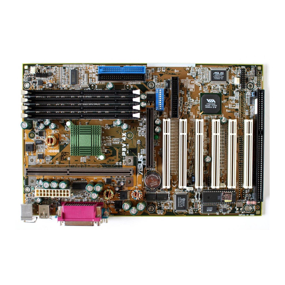
Page 12: P3V4X Motherboard Components
2. FEATURES 2.2 P3V4X Motherboard Components See opposite page for locations. Location Processor Support Slot 1 for Coppermine/Katmai/Mendecino Processors ..2 66MHz to 150MHz bus support (16 external clock settings) Chipsets VIA VT82C694X System Controller ......3 VIA VT82C596B PCI to ISA Bridge ......9 2 Mbit Programmable Flash EEPROM ...... - Page 13 2. FEATURES P3V4X Motherboard Component Locations ASUS P3V4X User’s Manual...
-
Page 14: Hardware Setup
3. HARDWARE SETUP 3.1 P3V4X Motherboard Layout 19.2cm (7.6in) T: Mouse PS2KBMS B: Keyboard PWR_FAN CPU_FAN T: USB1 B: USB2 COM1 VT82C694X Chipset COM2 JTPWR P3V4X CLRTC Accelerated Graphics Port CR2032 3V Lithium Cell (CMOS Power) PLED2 1 2 3 4 5... -
Page 15: Layout Contents
40 ATX Power / Soft-Off Switch Lead (2 pins) 23) RESET (PANEL) p. 40 Reset Switch Lead (2 pins) The optional onboard hardware monitor uses the address 290H-297H so legacy ISA cards must not use this address otherwise conflicts will occur. ASUS P3V4X User’s Manual... -
Page 16: Hardware Setup Procedure
1. Frequency Multiple 9. Frequency Selection P3V4X 2. Frequency Multiple 10. Frequency Selection 3. Frequency Multiple 4. Frequency Multiple 5. AGP Frequency Selection 6. AGP Frequency Selection 7. Frequency Selection 8. Frequency Selection P3V4X DIP Switches ASUS P3V4X User’s Manual... - Page 17 =DRAM Freq. x1 =DRAM Freq. x1 =DRAM Freq. x2/3 1 2 3 4 7 8 9 10 1 2 3 4 7 8 9 10 AGP Bus Freq. Auto =DRAM Freq. x1/2 Mode P3V4X AGP Bus Frequency Setting ASUS P3V4X User’s Manual...
- Page 18 Voltage Regulator Output Selection (VID) is not required for Pentium III/II processors because they send signals directly to the onboard power regulator. WARNING! Frequencies above 133MHz exceed the specifications for the on- board chipset and are not guaranteed to be stable. ASUS P3V4X User’s Manual...
- Page 19 Pentium II/Celeron 300MHz 4.5x 66MHz [OFF][OFF][ON][ON] [OFF][ON][OFF][ON] [ON][OFF] Pentium II/Celeron 266MHz 4.0x 66MHz [OFF][OFF][ON][ON] [ON][ON][OFF][ON] [ON][OFF] Pentium II 233MHz 3.5x 66MHz [OFF][OFF][ON][ON] [OFF][OFF][ON][ON] [ON][OFF] For updated processor settings, visit the ASUS web site (see ASUS CONTACT INFORMATION) ASUS P3V4X User’s Manual...
-
Page 20: System Memory (Dimm)
MHz, use only PC100- or PC133-compliant DIMMs; for the system bus to operate at 133MHz, use PC133-compliant DIMMs. • ASUS motherboards support SPD (Serial Presence Detect) DIMMs. This is the memory of choice for best performance vs. stability. • SDRAM chips are generally thinner with higher pin density than EDO (Extended Data Output) chips. -
Page 21: Dimm Memory Installation Procedures
88 Pins P3V4X 60 Pins 20 Pins P3V4X 168-Pin DIMM Memory Sockets The DIMMs must be 3.3Volt unbuffered SDRAMs. To determine the DIMM type, check the notches on the DIMMs (see figure below). 168-Pin DIMM Notch Key Definitions (3.3V) DRAM Key Position... - Page 22 3. HARDWARE SETUP (This page was intentionally left blank.) ASUS P3V4X User’s Manual...
-
Page 23: Central Processing Unit (Cpu)
SECC, or a Celeron™ processor packaged in a Single Edge Processor Pack- age (SEPP). An ASUS S370 Series CPU card can allow Socket 370 processors to be used on ASUS motherboards with a Slot 1 connector. (See 7.1 ASUS S370 Series CPU Cards for instructions on using this card.) -
Page 24: Attaching The Heatsink
SECC2 heatsink and fan except that the clamping design is different. WARNING! Make sure the heatsink is mounted tightly against the SECC2, SECC, or SEPP; otherwise, the CPU will overheat. You may install an auxiliary fan to provide adequate circulation across the processor’s passive heatsink. ASUS P3V4X User’s Manual... -
Page 25: Installing The Universal Retention Mechanism
URM to be installed improperly but will also damage the URM. 5. Push the four retainer pins completely down into the black fastener sleeves until the head of each pin is securely seated. ASUS P3V4X User’s Manual... -
Page 26: Installing The Processor
Lock hole CPU fan CPU fan cable to cable to fan fan connector connector 3. If your URM is of type A, make sure the locks are in the locked position as shown. Locked Position (push upward) ASUS P3V4X User’s Manual... -
Page 27: Removing The Processor
RPM and use the alert function with the Intel LANDesk Client Manager (LDCM) or the ASUS PC Probe software. SECC Heatsink & Fan SECC2 Heatsink & Fan NOTE: The SEPP heatsink and fan (for Intel Celeron processors) is similar to the SECC2 heatsink and fan except that the clamping design is different. -
Page 28: Precautions
4. There is no visible gap between the processor die and heatsink. The thermal interface material should be continuous with no through-holes or debris. Example of an incorrectly installed retention clip Example of a correctly installed retention clip ASUS P3V4X User’s Manual... -
Page 29: Expansion Cards
— PCI slot 4 — — — shared PCI slot 5 — — — shared PCI slot 6 — — shared — AGP slot shared shared — — Onboard USB controller — — — shared ASUS P3V4X User’s Manual... -
Page 30: Standard Interrupt Assignments
To simplify this process, this motherboard complies with the Plug and Play (PNP) specification which was developed to allow automatic system configuration when- ever a PNP-compliant card is added to the system. For PNP cards, IRQs are as- signed automatically from those available. ASUS P3V4X User’s Manual... -
Page 31: Assigning Dma Channels For Isa Cards
ISA and DMA x Used By ISA for those IRQs and DMAs you want to reserve). 3.7.4 Accelerated Graphics Port (AGP) This motherboard provides an accelerated graphics port (AGP) slot to support AGP graphics cards. P3V4X P3V4X Accelerated Graphics Port (AGP) ASUS P3V4X User’s Manual... -
Page 32: External Connectors
This connection is for a standard keyboard using an PS/2 plug (mini DIN). This connector will not allow standard AT size (large DIN) keyboard plugs. You may use a DIN to mini DIN adapter on standard AT keyboards. PS/2 Keyboard (6-pin Female) ASUS P3V4X User’s Manual... - Page 33 COM 1 COM 2 Serial Ports (9-pin Male) 5. Universal Serial BUS Port Connectors 1 & 2 (Two 4-pin female) Two USB ports are available for connecting USB devices. USB 1 Universal Serial Bus (USB) 2 ASUS P3V4X User’s Manual...
- Page 34 (Pin 5 is removed to prevent inserting in the wrong orienta- tion when using ribbon cables with pin 5 plugged). NOTE: Orient the red stripe of the floppy disk drive cable to Pin 1. P3V4X Floppy Drive Connector Pin 1 P3V4X Floppy Disk Drive Connector ASUS P3V4X User’s Manual...
- Page 35 2-pin plug. P3V4X IDELED P3V4X IDE Activity LED 9. Wake-On-Ring Connector (2-pin WOR) This connector connects to internal modem cards with a Wake-On-Ring output. The connector powers up the system when a ringup packet or signal is received through the internal modem card.
- Page 36 CPU fan if these pins are incorrectly used. These are not jumpers, do not place jumper caps over these pins. Power Supply Fan CPU Fan Power P3V4X Chassis Fan Power P3V4X 12Volt Cooling Fan Power ASUS P3V4X User’s Manual...
- Page 37 Back View Front View P3V4X IRTX (NC) IRRX For the infrared feature to be available, you must connect the optional Infrared (IrDA) module to the motherboard. P3V4X Infrared Module Connector ASUS P3V4X User’s Manual...
- Page 38 14. Power Supply Thermal Sensor Connector (2-pin block JTPWR) If you have a power supply with thermal monitoring, connect its thermal sensor cable to this connector. Power Supply Thermal Sensor Connector JTPWR P3V4X P3V4X Thermal Sensor Connector ASUS P3V4X User’s Manual...
- Page 39 NOTE: When the chassis is opened, connect/short the Chassis Signal pin to the +5VSB pin. When the chassis is closed, connect/short the Chassis Signal pin to the Ground pin. P3V4X CHASSIS P3V4X Chassis Intrusion Alarm Lead ASUS P3V4X User’s Manual...
- Page 40 Speaker Keyboard Lock Connector Power LED P3V4X Message LED Reset SW ATX Power Switch* SMI Lead Requires an ATX power supply. P3V4X System Panel Connections ASUS P3V4X User’s Manual...
-
Page 41: Power Connection Procedures
No DRAM installed or detected One long beep followed by Video card not found or video card three short beeps memory bad High frequency beeps when CPU overheated system is working System running at a lower frequency ASUS P3V4X User’s Manual... - Page 42 Down, and then click Shut down the computer?. The power supply should turn off after Windows shuts down. NOTE: The message “You can now safely turn off your computer” will not appear when shutting down with ATX power supplies. ASUS P3V4X User’s Manual...
-
Page 43: Bios Setup
4. In DOS mode, type A:\AFLASH <Enter> to run AFLASH. IMPORTANT! If “unknown” is displayed after Flash Memory:, the memory chip is either not programmable or is not supported by the ACPI BIOS and there- fore, cannot be programmed by the Flash Memory Writer utility. ASUS P3V4X User’s Manual... -
Page 44: Updating Bios Procedures (Only When Necessary)
<Enter>. 4.1.2 Updating BIOS Procedures (only when necessary) 1. Download an updated ASUS BIOS file from the Internet (WWW or FTP) (see ASUS CONTACT INFORMATION on page 3 for details) and save to the disk you created earlier. 2. Boot from the disk you created earlier. - Page 45 BIOS file you saved to disk above. If the Flash Memory Writer utility was not able to successfully update a complete BIOS file, your system may not be able to boot up. If this happens, your system will need servicing. ASUS P3V4X User’s Manual...
- Page 46 4. BIOS SETUP (This page was intentionally left blank.) ASUS P3V4X User’s Manual...
-
Page 47: Bios Setup Program
POST. NOTE: Because the BIOS software is constantly being updated, the following BIOS screens and descriptions are for reference purposes only and may not re- flect your BIOS screens exactly. ASUS P3V4X User’s Manual... -
Page 48: Bios Menu Bar
Brings up a selection menu for the highlighted field <Home> or <PgUp> Moves the cursor to the first field <End> or <PgDn> Moves the cursor to the last field <F5> Resets the current screen to its Setup Defaults <F10> Saves changes and exits Setup ASUS P3V4X User’s Manual... -
Page 49: General Help
Item Specific Help window located to the right of each menu. This window displays the help text for the currently highlighted field. NOTE: The item heading in square brackets represents the default setting for that field. ASUS P3V4X User’s Manual... -
Page 50: Main Menu
This is required to support older Japanese floppy drives. Floppy 3 Mode support will allow reading and writing of 1.2MB (as opposed to 1.44MB) on a 3.5-inch diskette. Configuration options: [Disabled] [Drive A] [Drive B] [Both] ASUS P3V4X User’s Manual... -
Page 51: Primary & Secondary Master/Slave
Primary IDE hard disk drives must have its partition set to active (also possible with FDISK). Other options for the Type field are: [None] - to disable IDE devices ASUS P3V4X User’s Manual... - Page 52 NOTE: To make changes to this field, the Type field must be set to [User Type HDD] and the Translation Method field must be set to [Manual]. ASUS P3V4X User’s Manual...
- Page 53 IDE devices. Set to [Disabled] to suppress Ultra DMA capability. NOTE: To make changes to this field, the Type field must be set to [User Type HDD]. Configuration options: [0] [1] [2] [3] [4] [Disabled] ASUS P3V4X User’s Manual...
-
Page 54: Keyboard Features
This field sets the time interval for displaying the first and second charac- ters. Configuration options: [1/4 Sec] [1/2 Sec] [3/4 Sec] [1 Sec] Language [English] This allows selection of the BIOS’ displayed language. Configuration op- tions: [English] ASUS P3V4X User’s Manual... - Page 55 Disk] [All but Disk/Keyboard] Installed Memory [XXX MB] This field displays the amount of conventional memory detected by the sys- tem during bootup. You do not need to make changes to this field. This is a display only field. ASUS P3V4X User’s Manual...
-
Page 56: Advanced Menu
This field determines whether the memory clock frequency is set to be in synchronous or asynchronous mode with respect to the System/PCI Fre- quency. The options displayed in the popup menu vary according to the System/PCI Frequency (MHz). ASUS P3V4X User’s Manual... - Page 57 [Disabled] [Enabled] [Auto] OS/2 Onboard Memory > 64M [Disabled] When using OS/2 operating systems with installed DRAM of greater than 64MB, you need to set this option to [Enabled]; otherwise, leave this on [Disabled]. Configuration options: [Disabled] [Enabled] ASUS P3V4X User’s Manual...
-
Page 58: Chip Configuration
[User Define]. SDRAM RAS to CAS Delay This controls the latency between the SDRAM active command and the read/write command. NOTE: To make changes to this field, the SDRAM Configuration field must be set to [User Define]. ASUS P3V4X User’s Manual... - Page 59 533MB/s even if you are using an AGP 4x card. Configuration options: [1X Mode] [2X Mode] [4X Mode] Graphics Aperture Size [64MB] This feature allows you to select the size of mapped memory for AGP graphic data. Configuration options: [4MB] [8MB] [16MB] [32MB] [64MB] [128MB] [256MB] ASUS P3V4X User’s Manual...
- Page 60 Configuration options: [Both] [Primary] [Sec- ondary] [Disabled] Memory Hole At 15M-16M [Disabled] This field allows you to reserve an address space for ISA expansion cards that require it. Configuration options: [Disabled] [Enabled] ASUS P3V4X User’s Manual...
-
Page 61: I/O Device Configuration
If your system already has a second serial port connected to the onboard COM2 connector, it will no longer work if you enable the infrared feature. See IrDA-Compliant Infrared Module Connector in 3.8 Exter- nal Connectors. Configuration options: [Disabled] [Enabled] ASUS P3V4X User’s Manual... - Page 62 This field allows you to configure the parallel port DMA channel for the selected ECP mode. This selection is available only if you select [ECP] or [ECP+EPP] in Parallel Port Mode above. Configuration options: [1] [3] [Disabled] ASUS P3V4X User’s Manual...
-
Page 63: Pci Configuration
[Disabled] will disable the motherboard’s Symbios SCSI BIOS so that the BIOS on an external Symbios SCSI card can be used. If your Symbios SCSI card does not have a BIOS, the Symbios SCSI card will not function. Con- figuration options: [Auto] [Disabled] ASUS P3V4X User’s Manual... - Page 64 ICU, you must set the field for that IRQ to [Yes]. For example: If you install a legacy ISA card that requires IRQ 10, then set IRQ10 Used By ISA to [Yes]. Configuration options: [No/ICU] [Yes] ASUS P3V4X User’s Manual...
- Page 65 ISA card is using that channel. If you install a legacy ISA card that requires a unique DMA channel, and you are not using an ICU, you must set the field for that channel to [Yes]. Configuration options: [No/ICU] [Yes] PCI/PNP ISA UMB Resource Exclusion ASUS P3V4X User’s Manual...
-
Page 66: Shadow Configuration
ROMs on them, you will need to know which addresses the ROMs use to shadow them specifically. Shadowing a ROM reduces the memory available between 640K and 1024K by the amount used for this purpose. Configuration options: [Disabled] [Enabled] ASUS P3V4X User’s Manual... -
Page 67: Power Menu
Windows 3.x and Windows 95, you need to install Windows with the APM feature. For Windows 98 and later, APM is automatically installed. A battery and power cord icon labeled “Power Management” will appear in the “Control Panel.” Choose “Advanced” in the Power Management Properties dialog box. ASUS P3V4X User’s Manual... - Page 68 Regardless of the setting, holding the ATX switch for more than 4 seconds will power off the system. NOTE: This field is only effective in APM OS system. Configuration options: [Soft off] [Suspend] ASUS P3V4X User’s Manual...
-
Page 69: Power Up Control
Configuration options: [Disabled] [Enabled] IMPORTANT: This feature requires an optional network interface with Wake-On- LAN and an ATX power supply with at least 720mA +5V standby power. ASUS P3V4X User’s Manual... - Page 70 This allows an unattended or automatic system power up. You may config- ure your system to power up at a certain time of the day by selecting [Every- day] or at a certain time and day by selecting [By Date]. Configuration options: [Disabled] [Everyday] [By Date] ASUS P3V4X User’s Manual...
-
Page 71: Hardware Monitor
NOTE: If any of the monitored items is out of range, an error message will appear: “Hardware Monitor found an error. Enter Power setup menu for details”. You will then be prompted to “Press F1 to continue, DEL to enter SETUP”. ASUS P3V4X User’s Manual... -
Page 72: Boot Menu
This field allows you to select which ATAPI CD-ROM drive to use in the boot sequence. Pressing [Enter] will show the product IDs of all your con- nected ATAPI CD-ROM drives. Other Boot Device Select [INT18 Device (Network)] Configuration options: [Disabled] [SCSI Boot Device] [INT18 Device (Net- work)] ASUS P3V4X User’s Manual... - Page 73 40 or 80 tracks. Floppy drives with 1.44MB have 80 tracks. You may leave the default [Disabled] to save time if you are using 1.44MB floppy drives. Configuration options: [Disabled] [Enabled] Full Screen Logo [Enabled] Configuration options: [Disabled] [Enabled] ASUS P3V4X User’s Manual...
-
Page 74: Exit Menu
This option should only be used if you do not want to save the changes you have made to the Setup program. If you have made changes to fields other than system date, system time, and password, the system will ask for con- firmation before exiting. ASUS P3V4X User’s Manual... -
Page 75: Load Setup Defaults
This option saves your selections without exiting the Setup program. You can then return to other menus and make changes. After selecting this op- tion, all selections are saved and a confirmation is requested. Select [Yes] to save any changes to the non-volatile RAM. ASUS P3V4X User’s Manual... - Page 76 4. BIOS SETUP (This page was intentionally left blank.) ASUS P3V4X User’s Manual...
-
Page 77: Software Setup
When prompted to restart, select No and then follow the normal setup procedures later in this section. NOTE: The screen displays in this and the following section may not reflect exactly the screen contents displayed on your screen. ASUS P3V4X User’s Manual... -
Page 78: P3V Series Motherboard Support Cd
D:\ASSETUP.EXE (assuming that your CD-ROM drive is drive D:). 5.2.1 Installation Menu • Install ASUS PC Probe Vx.xx: Installs a smart utility to monitor your computer’s fan, temperature, and voltages. • Install PC-Cillin 98 Vx.xx: Installs the PC-cillin virus protection software. View the online help for more information. -
Page 79: Install Asus Pc Probe Vx.xx
Insert the Support CD that came with your motherboard into your CD-ROM drive or double-click the CD drive icon in My Computer to bring up the setup screen. NOTE: ASUS PC Probe will not run if another hardware monitoring utility is in- stalled. To uninstall any program, see 5.7 Uninstalling Programs. -
Page 80: Install Pc-Cillin 98 Vx.xx
(6) & (7) Select the preferred features by clicking the appropriate buttons. (5) Click here. (8) Insert a floppy disk and then click here. Once the Emergency Clean disk is created, click OK. (9) Click here and then click Finish to restart. ASUS P3V4X User’s Manual... -
Page 81: Install Adobe Acrobat Reader Vx.xx
CD drive icon in My Computer to bring up the setup screen. (1) Click here. (2) Click here. (3) Click here only after you have read the License Agreement. (4) Click here. (5) Click here and then click Finish to restart. ASUS P3V4X User’s Manual... -
Page 82: Via 4 In 1 Driver
(1) Click here. (2) Click here. (4) Select preferred options and then click here. (3) Click here. (5) Click here. (6) Click here. (8) Click here and then follow onscreen instructions to (7) Click heren. complete installation. ASUS P3V4X User’s Manual... -
Page 83: Uninstalling Programs
Add/Remove Programs is a basic component within Windows. You may use this function if a program does not provide its own uninstallation program. (1) Double-click here to open the Add/Remove Programs Properties dialog box. (2) Select the program to remove and click here. (3) Click here. ASUS P3V4X User’s Manual... - Page 84 5. SOFTWARE SETUP (This page was intentionally left blank.) ASUS P3V4X User’s Manual...
-
Page 85: Software Reference
ASUS Utility, and then click Probe Vx.xx. The PC Probe icon will appear on the taskbar’s system tray indicating that ASUS PC Probe is running. Clicking the icon will allow you to see the status of your PC. ASUS P3V4X User’s Manual... -
Page 86: Using Asus Pc Probe
6. SOFTWARE REFERENCE 6.1.2 Using ASUS PC Probe Monitoring Monitor Summary Shows a summary of the items being monitored. Temperature Monitor Shows the PC’s temperature. Temperature Warning threshold adjustment (Move the slider up to increase the threshold level or down to decrease... - Page 87 Information Hard Drives Shows the used and free space of the PC’s hard disk drives and the file allocation table or file system used. Memory Shows the PC’s memory load, memory usage, and paging file usage. ASUS P3V4X User’s Manual...
-
Page 88: Asus Pc Probe Task Bar Icon
Execute Program. 6.1.3 ASUS PC Probe Task Bar Icon Right-clicking the PC Probe icon will bring up a menu to open or exit ASUS PC Probe and pause or resume all system monitoring. When the ASUS PC Probe senses a problem... -
Page 89: Appendix
The following are pictures of the ASUS S370 Series CPU cards with black plastic retainers attached to the edges. The retainers are used to hold the ASUS S370 Series CPU cards in place using the motherboard’s Slot 1 retention mechanisms. -
Page 90: Using The Asus S370 Series Cpu Cards
3. Install the CPU fan. 4. Insert the ASUS S370 Series CPU cards into Slot 1 on the motherboard. The two fins on the sides of the ASUS S370 Series CPU cards must catch on the retention mechanism so that it locks in place. -
Page 91: Asus Pci-L101 Fast Ethernet Card
Motherboard type Other If you are using the ASUS PCI-L101 on this motherboard, leave the jumper on its default setting of “ASUS.” If you are using another brand of motherboard, set the jumper to “Other.” Connect the Wake on LAN (WOL) output signal to the motherboard’s WOL_CON to utilize the Wake-On-LAN feature of the motherboard. -
Page 92: Software Driver Support
A: To enable Wake-On-LAN function, your system requires an Ethernet LAN adapter card that can activate Wake-On-LAN function, a client with Wake-On-LAN capa- bility, and software such as LDCM Rev. 3.10 or up that can trigger wake-up frame. ASUS P3V4X User’s Manual... -
Page 93: Glossary
CPU. Bus master IDE driver and bus master IDE hard disk drives are required to support bus master IDE mode. Byte (Binary Term) One byte is a group of eight contiguous bits. A byte is used to represent a single alphanumeric character, punctuation mark, or other symbol. ASUS P3V4XUser’s Manual... - Page 94 PCI bus is a specification that defines a 32-bit data bus interface. PCI is a standard widely used by expansion card manufacturers. Peripherals Peripherals are devices attached to the computer via I/O ports. Peripheral devices allow your computer to perform an almost limitless variety of specialized tasks. ASUS P3V4X User’s Manual...
- Page 95 With USB, the traditional complex cables from back panel of your PC can be eliminated. ASUS P3V4XUser’s Manual...
- Page 96 ASUS P3V4X User’s Manual...
Need help?
Do you have a question about the P3V4X and is the answer not in the manual?
Questions and answers