Table of Contents
Advertisement
Quick Links
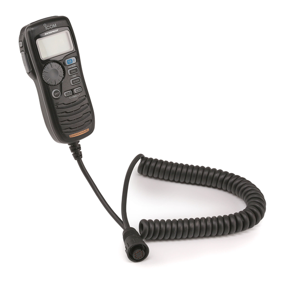
REMOTE-CONTROL MICROPHONE
HM-162E
These instructions are described when the HM-162E is connected to the IC-M603. Some operations or indications may be dif-
ferent as these instructions depending on the connecting transceiver.
z HM-162E supplied accessories
Accessories included with the HM-162E:
q Connection cable (OPC-1540*: 6 m; 20 ft) ....................... 1
w Mounting base .................................................................. 1
e Connector cap .................................................................. 1
r Microphone hanger .......................................................... 1
t Screws (M3 × 16; tapping) ............................................... 5
*: OPC 1540 has external speaker leads as illustrated at right.
(Yellow: Audio, Black: Speaker ground)
x Function display
!6
!5
q
BUSY
BUSY-25W
25W---
---INT
w
LOC-
LOC- --
RX
RX
--
DUP
DUP
e
SCRAM
SCRAM--TAG
TAG
r
NORMAL
NORMAL-SCAN
SCAN
t
[VOL]
-34
34°34.506N
34.506N
y
123
123°23.236W
23.236W
Local
Local--
--1:10
1:10- -
u
q BUSY/TRANSMIT INDICATOR
➥ "B B U U S S Y Y " appears when receiving a signal or when the
squelch opens.
➥ "T T X X " appears while transmitting.
w RX SPEAKER INDICATOR
Appears during the RX speaker mode.
e SCRAMBLER INDICATOR
"S S C C R R A A M M " appears when an optional voice scrambler is acti-
vated.
r SCAN INDICATOR
➥ "P P R R I I - - S S C C A A N N 1 1 6 6 " appears during Priority scan; "N N O O R R - -
M M A A L L S S C C A A N N " appears during Normal scan.
➥ "D D U U A A L L 1 1 6 6 " appears during dualwatch; "T T R R I I 1 1 6 6 " ap-
pears during tri-watch.
t SELECTOR STATUS INDICATOR
Indicates the [SELECTOR] active status;
"[ [ V V O O L L ] ] " appears when [SELECTOR] functions as the
audio volume.
"[ [ S S Q Q L L ] ] " appears when [SELECTOR] functions as the
noise squelch controller.
"[ [ D D I I A A L L ] ] " appears when [SELECTOR] functions as the
channel selector.
Icom, Icom Inc. and the
logo are registered trademarks of Icom Incorporated (Japan) in the United States, the United Kingdom, Germany, France, Spain, Rus-
sia and/or other countries. COMMANDMIC III is a trademark of Icom Incorporated (Japan) in the United states.
INSTRUCTIONS
Qty.
!4
!3
!2
INT---
---CALL
CALL
!1
!0
o
CALLING
CALLING
i
Thank you for purchasing the HM-162E
CONTROL MICROPHONE
remote control microphone for use with the IC-M603
or else.
Please read the connected transceiver's instruction
manual carefully before installation and operation.
These instructions are just described the remote-
control operations only.
q
Black
Yellow
y POSITION INDICATOR
➥ Shows the GPS position data.
• "? ? ? ? " may blink every 2 sec. instead of position data when
the GPS position data is invalid. In this case, the last position
data is held for up to 23.5 hours.
• "? ? ? ? " may blink every 2 sec. instead of position data 4 hours
after the position data is input manually, up until 23.5 hours
have past.
➥ "N N o o P P o o s s i i t t i i o o n n " appears when no GPS receiver is con-
nected and no position data is input manually.
u TIME ZONE INDICATOR
➥ "L L o o c c a a l l " appears when the offset time data in the 'Set
up' menu is entered.
➥ "N N o o T T i i m m e e " appears when no GPS receiver is connected
and no time data is input manually.
i CHANNEL COMMENT INDICATOR
Channel comment appears, if programmed.
o CHANNEL NUMBER READOUT
Indicates the selected operating channel number.
!0 KEY LOCK INDICATOR
➥ Appears while the Key Lock function is in use.
➥ Blinks while the All Key Lock function is in use.
!1 LOW BATTERY INDICATOR
"
" blinks when the battery voltage drops to approx. 10 V
DC or below.
!2 CALL CHANNEL INDICATOR
"C C A A L L L L " appears when the call channel is selected.
!3 CHANNEL GROUP INDICATOR
Indicates whether an International "I I N N T T ," U.S.A. "U U S S A A ,"
DSC "D D S S C C " or ATIS "A A T T I I S S " channel is selected.
• Depending on the connected transceiver's version.
!4 DUPLEX INDICATOR
Appears when a duplex channel is selected.
• Duplex channel has a different TX and RX frequency.
!5 TAG CHANNEL INDICATOR
Appears when a tag channel is selected.
!6 POWER INDICATOR
➥ "2 2 5 5 W W " appears when high power is selected.
➥ "1 1 W W " appears when low power is selected.
1
REMOTE
. The COMMANDMIC III
TM
w
e
r
t
-
is a
Advertisement
Table of Contents

Related Manuals for Icom HM-162E


Summary of Contents for Icom HM-162E
- Page 1 These instructions are just described the remote- control operations only. These instructions are described when the HM-162E is connected to the IC-M603. Some operations or indications may be dif- ferent as these instructions depending on the connecting transceiver. z HM-162E supplied accessories Accessories included with the HM-162E: Qty.
-
Page 2: Panel Description
The optional HM-162E remotely controls the transceiver and ➥ Push to provides an optional Intercom function. toggle the DSC menu ON or OFF. ➥ While pushing [CLR], push this key to turn the HM-162E Top keys power ON and OFF. Back side i SCAN KEY [SCAN•TAG]... -
Page 3: Channel Selection
Selector’s action n Receiving and transmitting q Push [PWR] to turn power ON. The HM-162E has a selector dial, which works various func- w Set the audio and squelch levels. tions. ➥ Push [VOL/SQL•MONI ] for 1 sec. to activate the moni- ➥... -
Page 4: Call Channel Programming
, Call channel programming ⁄0 Setting TAG channels q While pushing [H/L], push [DIAL•DW ] several times to q While pushing [H/L], push BUSY-25W---INT---CALL select the desired channel group (depending on the con- LOCAL--DUP [DIAL•DW ] several times to SCRAM--TAG nected transceiver’s version). -
Page 5: Display Backlight
LOCARX the foghorn level, push [ENT]. SCRAM SCRAM-- --TAG speaker). The HM-162E emits a vibrating noise when this func- • The foghorn level is adjustable in NORMAL-SCAN NORMAL-SCAN tion is being used. This function is availabe depending on the FOGHORN... -
Page 6: Set Mode Programming
You can select the external speaker ON or OFF. When this set- position data will be held for 23.5 hours only. ting is set ON, HM-162E’s external speaker can be used in- stead of internal speaker. q Select and enter “P P o o s s i i t t i i o o n n I I n n p p u u t t ” in the DSC menu. -
Page 7: Distress Call
¤3 Distress call Transmitting DSC calls (continued) D D Transmitting an individual acknowledgement • The distress call is repeated every 3.5–4.5 min., until re- ceiving an ‘acknowledgement.’ “I I n n d d i i v v i i d d u u a a l l A A C C K K ” item appears after an individual call is •... -
Page 8: Received Messages
• After inputting the 9-digit MMSI number, push [ENT] or [16•C] to enter the ID name. • 1st digit must not be ‘0’ for a individual ID. CLEAN THE HM-162E THOROUGHLY WITH FRESH [For Group ID] WATER after exposure to water including salt, otherwise, •...
Need help?
Do you have a question about the HM-162E and is the answer not in the manual?
Questions and answers