
Related Manuals for Ikan MS21


Summary of Contents for Ikan MS21
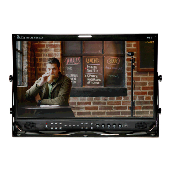
- Page 1 MS21 21.5" 3G-SDI Studio Monitor USER GUIDE 1.713.272.8822 support@ikancorp.com www.ikancorp.com © 2013 ikan Corporation. All right reserved...
-
Page 2: Table Of Contents
Contents Safety Instructions....................3 Front........................4 Rear........................6 MENU Description....................7 VIDEO........................9 DISPLAY 1......................10 DISPLAY 2......................12 COLOR.........................14 MARKER......................15 OSD........................17 AUDIO........................19 GPI........................21 SYSTEM......................23 USB Firmware Update..................25 External Remote Control..................26 List of Compatible Video Formats (HDMI/Composite)........28 List of Compatible Video Formats (SDI)............29 Specifications......................31 Dimensions......................32 Troubleshooting....................33 Warranty Information..................35 Modification of Product..................35 Caution on Menu Operation................35 Caution for Monitor Placement................35... -
Page 3: Safety Instructions
Safety Instructions • To help avoid damaging your monitor, connect only one power (AC or DC) in operation. • Rough handling of product may cause physical damage or malfunction. • Never insert anything metallic into the monitor openings. Doing so may create the danger of electric shock. -
Page 4: Front
Front Standby (Power) Input Switcher (SDI 1, SDI 2, HDMI/DVI) Analog Switch analog input in the order of CVBS1 -> CVBS2 -> CVBS3 -> SVIDEO -> YPbPr -> RGB -> VGA. WF/VS Waveform / Vectorscope display selection button. Marker On/Off Frame line generation button. - Page 5 Menu Enter Knob for Adjustment or Enter Knob used to adjust Brightness / Contrast / Chroma / Phase or Enter button. Headphone Jack...
-
Page 6: Rear
Rear AC Input Please check Power Cord, Power Voltage, Supply power for power input are suitable for the standard before use. Please do not mix AC power and DC power as it may cause the defects or fire. DC Input For DC power supply. -
Page 7: Menu Description
USB Port USB Firmware Update Port. MENU Description General Cautions for OSD menu or Display The menu may not be displayed even when user pressed Menu button if there's No Signal, or in unclear signal status. The menu selection may be saved for each input signal mode, so sometimes user should do menu selection again. -
Page 8: Video
VIDEO Brightness, Contrast, Chroma, Phase, Sharpness Adjust color representation values. SDI Switching Normal : Use Normal in general condition but the screen might be blinking on screen change when you use Matrix or Routing Switcher. Fast : Use Fast to minimize blinking on screen change. NTSC Setup Select IRE among 0 or 7.5 (Default) HDMI UV Swap... -
Page 9: Display 1
DISPLAY 1 Aspect Set the aspect ratio of the screen. 16:9, 4:3, Native(Original) are selectable. This selection is ignored on 1080i, 1080p, 720p. 1:1 Scan On SD signals(Not HD), Set this on to display picture in 1:1 pixel mapping. Turn this mode on to adjust aspect ratio with the ratio value in the source signal. Waveform Display Select waveform display mode. - Page 10 Waveform Intensity Adjust waveform intensity. Waveform & Vector Size Adjust size of Waveform & Vector. Waveform & Vector Blend Adjust transparency value of Waveform & Vector. False Color Turn False Color mode on to check exposure levels of the picture.
-
Page 11: Display 2
DISPLAY 2 Exposure Range Check (Video Range Check) Checks Y, C level and displays over-exposed or under-exposed area on screen. The base value can be Y, Cb, or Cr. Y Range Max / Min Set Y range value for range check. C Range Max / Min Set C range value for range check. - Page 12 Focus Assist Color Set brush color of focus assist mode among Blue, Green, and Red.
-
Page 13: Color
COLOR Color Temperature Select color temperature among 3200K, 5400K, 6500K, 9300K or USER. (Gain and Offset menu are displayed on USER temperature only) Red/Green/Blue Gain (USER mode only) R,G,B gains are adjustable on User mode. Red/Green/Blue Offset (USER mode only) R,G,B offsets are adjustable on User mode. -
Page 14: Marker
MARKER Marker Ratio Select one of preset markers or user marker. To display marker, press Marker button in front of the monitor. Center Marker Set preference to display center marker or not. Safety Area 16:9 Adjust size of the safety area when marker displayed on 16:9 screen. Safety Area 4:3 Adjust size of the safety area when marker displayed on 4:3 screen. - Page 15 User Marker H1 / User Marker H2 / User Marker V1 / User Marker V2 Set user marker’s position. H1 for left, H2 for right, V1 for top, V2 for bottom. The positions are saved as the selected marker name such as USER1.
-
Page 16: Osd
Timecode Display On/Off Timecode Position Set the position of timecode. OSD Display Time Set menu display time (seconds) MENU Position Set menu position among Left Top, Right Top, Left Bottom, Right Bottom and Center. V-Chip SD-SDI, Composite signal might contain V-Chip data. Turn this mode on to display V-Chip information on screen. - Page 17 Service 1: general captions. Service 2: translated captions. Service 3,4: not assigned. CC608 StartLine Display line of captions are selectable by user. (e.g. 13) Internal Pattern Show internal test pattern such as color bars. Turn this mode off to display general pictures from input port.
-
Page 18: Audio
AUDIO Embedded Audio Left Select audio channel for left (Ch 1 ~ 15) Embedded Audio Right Select audio channel for right (Ch 2 ~ 16) Audio Level Meter Turns on/off audio level meters. Level Meter Size Select the size of the meters : Small or Large. Level Meter Position Select the position of the meters : Upper or Lower. -
Page 19: Gpi
GPI Control Turns on/off external monitor control function. GPI Port 1,2,3,4,5,6 Assigns each GPI port’s function. (e.g. SDI 1 input, HDMI input, Tally Red) See EXTERNAL REMOTE CONTROLLING section for details. Remote ID Number Assigns the ID for the monitor to control through serial port. 0 to 99 can be assigned. -
Page 20: System
SYSTEM Function 1,2,3,4 Assigns a function to each function button. See FRONT section for detail. Backlight Set the backlight intensity from 0 to 40. An LCD panel requires more than 30 minutes to be settled to a new backlight value. Front Button LED Set front LEDs on/off status. - Page 21 Firmware Version This version number is required when you request for service. Operating Time This indicates total hours that the monitor operated.
-
Page 23: External Remote Control
External Remote Control Connecting GPI Port(RJ-45) Update Port (RJ-11) Update (RJ-11) Update Terminal Assignment 1 PIN 4 PIN 2 PIN 5 PIN 3 PIN 6 PIN * Turn power off first and connect update cable when you update monitor firmware. Remote Control / GPI Port Pin Assignments Remote (RJ-45) Remote PIN Assignment... - Page 24 Assignable functions are listed below. Function Name Description SDI-1 Input Switches the input to SDI-1 SDI-2 Input Switches the input to SDI-2 HDMI Input Switches the input to HDMI YPbPr Input Switches the input to YPbPr CVBS-1 Input Switches the input to CVBS-1 CVBS-2 Input Switches the input to CVBS-2 CVBS-3 Input...
-
Page 25: List Of Compatible Video Formats (Hdmi/Composite)
List of Compatible Video Formats (HDMI/Composite) INPUT Signal Input Composite HD-YPbPr Formats SD-RGB HDMI NTSC 720*576/50i 720*480/59.94i 720*480/60i 720*576/50p 720*480/59.94p 720*480/60p 1280*720/23.98p 1280*720/24p 1280*720/25p 1280*720/29.97p 1280*720/30p 1280*720/50p 1280*720/59.94p 1280*720/60p 1920*1080/50i 1920*1080/59.94i 1920*1080/60i 1920*1080/23.98p 1920*1080/24p 1920*1080/25p 1920*1080/29.97p 1920*1080/30p 1920*1080/50p 1920*1080/59.94p 1920*1080/60p... -
Page 26: List Of Compatible Video Formats (Sdi)
List of Compatible Video Formats (SDI) Component Input Signal Composite/ YPbPr Formats S-Video NTSC √ √ 525/60i (SD) √ √ √ 625/50i (SD) √ √ √ 720*480/59.94p √ √ 720*576/50p √ √ 1280*720/23.98p 1280*720/24p 1280*720/50p √ √ √ 1280*720/59.94p √ √... -
Page 27: Specifications
Specifications BSM-182 i BSM-212 i BSM-242 i 2 x BNC HD/SD-SDI, 1.485G/270M 3 x BNC Analog(YPbPr/CVBS/S-Video/RGB) Input 1 x HDMI HDMI (with HDCP v.1.1), 19pin Female 1 x DVI DVI-I, 24pin, Female 3 x BNC Analog(YPbPr/CVBS/S-Video/RGB) Output 2 x BNC HD/SD-SDI, 1.485G/270M 1 x Phone Jack In Line In(Stereo) -
Page 28: Dimensions
Dimensions BSM-182i (WxHxD) 438.4 x 310.8 x 66.4mm (17.2 x 12.2 x 2.6 inches) BSM-212i (WxHxD) 505.6 x348.0 x 59.2mm (19.9 x 13.7 x 2.3 inches) BSM-242i (WxHxD) 553.4 x 403.5 x 62.5 mm (21.7 x 15.8 x 2.4 inches) - Page 29 www.ikancorp.com CONDITIONS OF WARRANTY SERVICE • Free service for one year from the day of purchase if the problem is caused by manufacturing errors. • The components and maintenance service fee will be charged if the warranty period has expired. Free Service will not be Provided in the Following Situations: (* Even if the product is still within the warranty period.) •...
Need help?
Do you have a question about the MS21 and is the answer not in the manual?
Questions and answers