Table of Contents
Advertisement
Quick Links
Serial Number
2.4L
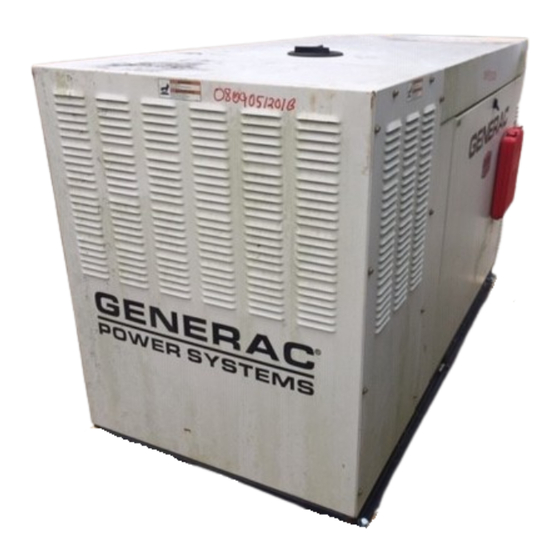
25kW
Models
STANDBY GENERATOR
OWNER'S MANUAL
A new standard of reliability
Not intended for use in critical life support applications.
—CAUTION—
ONLY QUALIFIED ELECTRICIANS OR CONTRACTORS SHOULD ATTEMPT INSTALLATION!
DEADLY EXHAUST FUMES. OUTDOOR INSTALLATION ONLY!
This manual should remain with the unit.
0G4159
No.
Part
05/07
A
Rev.
Cover112
Advertisement
Table of Contents

Related Manuals for Generac Power Systems 2.4L


Summary of Contents for Generac Power Systems 2.4L
-
Page 1: Serial Number
Serial Number 2.4L 25kW Models STANDBY GENERATOR OWNER'S MANUAL A new standard of reliability Not intended for use in critical life support applications. —CAUTION— ONLY QUALIFIED ELECTRICIANS OR CONTRACTORS SHOULD ATTEMPT INSTALLATION! DEADLY EXHAUST FUMES. OUTDOOR INSTALLATION ONLY! This manual should remain with the unit. -
Page 2: Table Of Contents
SECTION SAFETY RULES ... 1-1 INTRODUCTION ...1-3 Read this Manual Thoroughly ...1-3 Operation and Maintenance ...1-3 How to Obtain Service ...1-3 IDENTIFICATION RECORD ...2-1 Data Label ...2-1 EQUIPMENT DESCRIPTION ...3-1 Equipment Description ...3-1 Engine Oil Recommendations ...3-1 Coolant Recommendations...3-1 ENGINE PROTECTIVE DEVICES ...4-1 High Coolant Temperature Switch ...4-1 Low Coolant Level Sensor ...4-1 Low Oil Pressure Switch ...4-1... -
Page 3: Safety Rules
SAVE THESE INSTRUCTIONS – The manufacturer suggests that these rules for safe operation be copied and posted in potential hazard areas. Safety should be stressed to all operators, potential operators, and service and repair technicians for this equipment. WARNING: The engine exhaust from this product contains chemicals known to the state... -
Page 4: Fire Hazards
• Before performing any maintenance on the gen- erator, disconnect its battery cables to prevent accidental start-up. Disconnect the cable from the battery post indicated by a NEGATIVE, NEG or (–) first. Reconnect that cable last. • Never use the generator or any of its parts as a step. -
Page 5: Introduction
INTRODUCTION Thank you for purchasing this model of the standby generator set product line. Every effort was expended to make sure that the information and instructions in this manual were both accurate and current at the time the manual was written. -
Page 6: Identification Record
IDENTIFICATION RECORD DATA LABEL Every generator set has a DATA LABEL that contains important information pertinent to the generator. The data label, which can be found attached to the gen- erator’s lower connection box, lists the unit’s serial number and its rated voltage, amps, wattage capacity, phase, frequency, rpm, power factor, etc. -
Page 7: Equipment Description
EQUIPMENT DESCRIPTION This equipment is a revolving field, alternating cur- rent generator set. It is powered by a gaseous fueled engine operating at 1800 rpm for 4-pole direct drive units, 3600 rpm for 2-pole direct drive units and 2300 - 3000 rpm for quiet drive gear units. See the Specifications section for exact numbers. -
Page 8: Engine Protective Devices
ENGINE PROTECTIVE DEVICES The standby generator may be required to operate for long periods of time without an operator on hand to monitor such engine conditions as coolant tempera- ture, oil pressure or rpm. For that reason, the engine has several devices designed to protect it against potentially damaging conditions by automatically shutting down the unit when the oil pressure is too low, the coolant temperature is too high, the coolant... -
Page 9: Fuel Systems
FUEL SYSTEM FUEL REQUIREMENTS The standby generator may be equipped with one of the following fuel systems: • Natural gas fuel system • Propane vapor (PV) fuel system The Manual Drawing Listing that is affixed to the unit includes the “Identification Code,” which may be used to identify the type of fuel system installed on the unit. -
Page 10: Specifications
SPECIFICATIONS GENERATOR Type ... Synchronous Rotor Insulation ...Class F Stator Insulation ... Class H Total Harmonic Distortion ...<5% Telephone Interference Factor (TIF) ...< 50 Alternator Output Leads 3-phase ... 6-wire Bearings ...Sealed Ball Coupling ...Flexible Disc Load Capacity (Standby Rating) ...25kW* NOTE: Generator rating and performance in accordance with ISO8528-5, BS5514, SAE J1349, ISO3046 and DIN 6271 Standards. -
Page 11: Cold Weather Kit
CONTROL PANEL GENERATOR CONNECTION CIRCUIT BREAKER Battery Charger Input 120 Volt + Neutral Ground Level STUB-UP AREA Concrete Slab See Install Dwg for Dimensions COLD WEATHER KIT For cold climates, optional cold weather kit (part number 0F6148) is recommended. The kit includes: •... -
Page 12: General Information
GENERATOR AC LEAD CONNECTIONS See “Voltage Codes”. This generator may be rated at any one of three voltages, either single-phase or three-phase. The electrical wires in the unit’s AC con- nection (lower) panel should be installed according to the number of leads and the voltage/phase required for the application. -
Page 13: Installation
INSTALLATION Refer to the separate “Installation Guide” supplied with the unit. PREPARATION BEFORE START-UP The instructions in this section assume that the standby generator has been properly installed, ser- viced, tested, adjusted and otherwise prepared for use by a competent, qualified installation contractor. Be sure to read the “Safety Rules”, as well as all other safety information in this manual, before attempting to operate this (and related) equipment. -
Page 14: Start-Up Checklist
• Battery charger connection to 120 VAC. • Communication wires connected between transfer switch and generator (HTS only). • Unit secured to pad. START-UP CHECKLIST Before working on the generator, ensure the fol- lowing: • The AUTO/OFF/MANUAL switch is in the OFF position. -
Page 15: Operation
GENERATOR CONTROL AND OPERATION Refer to the appropriate control panel operator’s manual for this unit. OPERATING UNIT WITH MANUAL TRANSFER SWITCH If the generator was installed in conjunction with a transfer switch capable of manual operation only, the following procedure applies. A manually operated transfer switch is one that will not provide automatic start-up and does not include an intelligence circuit. -
Page 16: Overload Protection For Engine Dc Electrical System
MAINTENANCE PERFORMED BY SERVICE FACILITIES Before working on the generator, ensure the fol- lowing: • The AUTO/OFF/MANUAL switch is in the OFF position. • The 15A fuse has been removed from the con- trol box. • The 120VAC supply to the battery charger is switched OFF . -
Page 17: Battery Fluid
• Remove oil dipstick and wipe dry with a clean, lint- free cloth. • Install oil dipstick, then remove again. • Oil should be between FULL and ADD marks. • If oil level is below the dipstick ADD mark, remove oil fill cap-. -
Page 18: Changing Engine Oil
CHANGING ENGINE OIL Refer to maintenance performed by service facilities for engine oil and filter change frequencies. Drain the oil while the engine is still warm from run- ning. This means warm up the engine, shut it down and drain immediately as follows: 1. -
Page 19: Miscellaneous Maintenance
MISCELLANEOUS MAINTENANCE CLEANING THE GENERATOR Keep the generator as clean and as dry as possible. Dirt and moisture that accumulates on internal gen- erator windings have an adverse effect on insulation resistance. Periodically clean generator exterior surfaces. A soft brush may be used to loosen caked on dirt. Use a vacuum system or dry, low pressure air to remove any accumulations of dirt. -
Page 20: Service Schedule
SERVICE SCHEDULE 30 KW - 150 KW STANDBY GAS ENGINE DRIVEN GENERATOR SETS The following is a recommended maintenance schedule for standby gas engine driven generator sets from 30kW to 150 kW in size. The established intervals in the schedule are the maximum recommended when the unit is used in an average service application. - Page 21 Maintenance Level 1 Tasks Recom- mended Comp. to be done Comp. to be done to be done (Date- monthly/ Initials) 10 hrs. 1. Disable the unit from operating per the first page warning. 2. Check the engine oil level. Adjust as necessary.
- Page 22 Maintenance Level 1 Tasks Recom- mended Comp. to be done Comp. to be done to be done (Date- monthly/ Initials) 10 hrs. 10. Check the engine accessory drive belts and fan coupling device if equipped for correct tension, wear, weather cracking, and damage.
- Page 23 Maintenance Level 1 Tasks Recom- mended Comp. to be done Comp. to be done to be done (Date- monthly/ Initials) 10 hrs. 18. Start and exercise the unit at full rated load (use a load bank if the site load is not enough) for at least 2 hours looking for leaks,...
-
Page 24: Troubleshooting
TROUBLESHOOTING GUIDE PROBLEM CAUSE Engine won’t crank. Engine cranks but won't start Engine starts hard, runs rough. Engine starts then shuts down. AUTO/OFF/MANUAL Switch at OFF, engine continues to run No AC output from generator. *Contact the nearest Authorized Dealer for assistance. Standby Generator Sets Troubleshooting 1. - Page 25 Standby Generator Sets Notes...
- Page 26 Standby Generator Sets Notes...
- Page 32 0G0056 ROTOR-2390-35KD1 CPL 0G1155 ROTOR-2390-35KD1 CPL (G2) 0F9677 ROTOR-2390-45KD1 CPL 0G0959 ROTOR-2390-45KD1 CPL (G2) 0G2101 ROTOR 25KW 1PH DIRECT 390 1800 0G1931 ROTOR 25KW 3PH DIRECT 390 1800 0G0057 STATOR-2390-35AD1 CPL 0F9664 STATOR-390 45K 2P 1PH DIRECT 0G0058 STATOR-2390-35KD1 CPL 0G0184 STATOR-2309-45-KD1 CPL 0G0059...
- Page 34 RIVET POP .125 X .275 SS 0E7358 SCREW PPPH HI-LO #4-24 X 3/8 052777 WASHER FLAT M3 0G1303C ASSY PCB R-200 1800 RPM 2.4L 0F1262 HOLDER FUSE WICKMANN 178.6150 0F1263 ADPTR RH SIDE WICKMAN 178.6191 0F1264 ADPTR LH SIDE WICKMAN 178.6192...
- Page 36 SPRING CLIP HOLDER .37-.62 0F9597 SUPPORT RH ENGINE 2.4L 022129 WASHER LOCK M8-5/16 026204 WASHER SHAKEPROOF INT 5/16 022145 WASHER FLAT 5/16-M8 ZINC 045771 NUT HEX M8-1.25 G8 CLEAR ZINC 0F9596 SPACER ENGINE MOUNT (2.4L G1) 0F9596A SPACER LH ENGINE MOUNT (2.4L G2)
- Page 38 0F3408B BATTERY TRAY C1 CPL 0F3411 STRAP BATTERY RETAINMENT 025507 WASHER SHAKEPROOF EXT 7/16 STL 052212 SCREW HHC M10-1.25 X 25 G8.8 046526 WASHER LOCK M10 022131 WASHER FLAT 3/8-M10 ZINC 050331A BATTERY POST COVER RED + 050331 BATTERY POST COVER BLACK - 038805Y CABLE BATTERY BLACK #1 X 18.00 03880400AE...
- Page 40 ADAPTER CARBURETOR W/PVC CONN 0C8127 ELEMENT AIR CLEANER 052619 SCREW HHC M5-0.8 X 20 G8.8 022127 NUT HEX 1/4-20 STEEL 062974 STUD TH 1/4-20 X 4-1/2 G2 ZNC 0G0190 PLATE, AIR CLEANER TOP 2.4L 037561 NUT WING 1/4-20 NYLK 022097 WASHER LOCK M6-1/4...
- Page 42 0G0951 1(REF) GASKET EXHAUST MANIFOLD 0G3910 EXHAUST MANIFOLD G2 (MACHINE) (35KW & 45KW) 0G0608 MANIFOLD EXHAUST (MACHINED) (25KW ONLY) 0F9965E FLEX PLATE 2 POLE 2.4L G2 0D2244M ASSY MAGPICKUP(3/8-24 MALE) 0F9420 ADAPTER ENGINE 2.4L MACHINE 0E9747 STARTER, 12 VOLT 0G1472A...
- Page 44 0F9529 WELDMENT RADIATOR SUPPORT 2.4L 0F2608 RADIATOR 598 X 568 X 49 CPL RH 0F5263 V-BELT 31/64" X 57-3/8" 046526 WASHER LOCK M10 059981 SCREW HHC M10-1.5 X 30 G10.9 0F2776A BRACKET, SIGNAL CONDITIONER (USED ONLY WITH QTA PRODUCT) 0F5050A...
- Page 50 0F9794 MUFFLER 7" X 9" X 18-1/2" 2" IN/OUT 0G0113 EXHAUST ELBOW 2 1/4 OD 2 1/2OD 0G1007 BRACKET MUFFLER 0F2830 MUFFLER BRACKET STIFFENER 0F2962 MUFFLER STRAP 080762 BOLT U 3/8-16 X 2.62 0E0170A EXHAUST BLANKET 988MM (C2) 0C2454 SCREW THF M6-1 X 16 N WA Z/JS 0G0776 PIPE EXHAUST G2 0G0007...
- Page 67 C2 UNITS 0F9832 SHIELD CONN BOX C2 0F9832GGS0R SHIELD CONTROL STAND C2 0C2454 SCREW THF M6-1 X 16 N WA Z/JS C3 UNITS 0F9832B SHIELD CONTROL STAND C3 0F9832KGS0R SHIELD CONTROL STAND C3 0C2454 SCREW THF M6-1 X 16 N WA Z/JS C4 UNITS 0F9832A SHIELD CONTROL STAND C4...
- Page 68 04/07 Rev. BackPg001...
Need help?
Do you have a question about the 2.4L and is the answer not in the manual?
Questions and answers