Table of Contents
Advertisement
Quick Links
Advertisement
Table of Contents

Subscribe to Our Youtube Channel
Related Manuals for Xantrex Smart mini


Summary of Contents for Xantrex Smart mini
- Page 1 Link 20 Owner's Manual Xantrex Link 20 Battery Monitor...
-
Page 2: Table Of Contents
TABLE OF CONTENTS Introduction, Battery Facts Front Panel Description Link 20 Using Your Reading Dual Watch Light Bars Link 20 Battery Management Battery Capacity Testing Link 20 Synchronizing to Batteries Setup 10–20 Setting Up Functions 16–20 How to RESET your unit DATA: Your Battery History LOCK: Kid proofing Peukert (High Discharge Rate) Exponents... - Page 3 LINK 20 INTRODUCTION Congratulations! You have purchased the world's only Dual Watch battery monitor. In order to understand, use, and install it, PLEASE read this manual. It provides important information. Please contact us with suggested improvements. For Link 20 installation, operation, warranty support, and repair questions, please contact Xantrex.
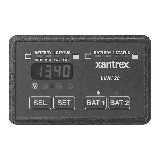
- Page 4 FRONT PANEL OF YOUR LINK 20 The exclusive Dual Watch light bars give you battery state-of-charge information at a glance. It's easy to train your whole crew, even the kids, to turn off loads and start charging when the light bar shows two yellow lights. When the light bar is green, you've got plenty of energy.
-
Page 5: Using Your Link 20
USING YOUR LINK 20 STATUS LIGHTS These green lights tell you what units are displayed. Volts is the electric potential to do work. Voltage is useful to assess the approximate state-of-charge and to check for proper charging. Examples: An at-rest, fully charged battery will show about 12.8 V. -
Page 6: Light Bars
READING THE LIGHT BARS Above the Link 20 numeric display are two light bars, each with four lights. They show you battery state- of-charge at a glance. Four green lights means your battery is nearly full (80–100% charged). A single flashing red light means it's nearly discharged. Light bar scaling is independently settable. -
Page 7: Link 20 Battery Management
LINK 20 BATTERY MANAGEMENT SIMPLE BATTERY MANAGEMENT RULE: Recharge When the Battery is 50% Discharged! The Link 20 is a guide to the battery's state of charge. Our Mid-Capacity Rule says you should begin charging when your Link 20 shows that 50% (or more) of battery capacity has been consumed. -
Page 8: Battery Capacity Testing
BATTERY CAPACITY TESTING Your Link 20 can be used to conduct periodic capacity tests that tell you the actual amount of energy your batteries can store. A capacity test should start with a battery that has been properly charged and equalized. The objective is to find the maximum available capacity. - Page 9 SYNCHRONIZING TO YOUR BATTERY A charged battery has zero amp hours removed. Synchronizing your Link 20 to read zero when the battery is charged ensures that you always know the net number of amp hours removed. There are two ways to synchronize your Link 20: 1) Install the Link 20 on a fully charged battery and it will be in sync.
-
Page 10: Setup
SETUP PROCEDURES Your Link 20 comes with default values chosen to work with most systems. Normally the only values that need to be i4.25 changed are the battery capacity, battery type (liquid or gelled), and high discharge rate compensation (Peukert) exponent. Please be sure you understand each function before changing the factory default values outlined below. - Page 11 USING SET AND SEL BUTTONS Pressing and holding the SET button for five seconds enters the Setup and SEL appears in the display, prompting you to press Advanced Functions modes. The word SEL the SEL button to choose what function you want to SELect. PRESS BAT 1 OR BAT 2 TO PICK THE BATTERY YOU WISH TO SET UP.
- Page 12 WHEN TO SET UP The C The Link 20 depends on correctly set Charged Parameters to stay in sync with battery state-of-charge, to automatically reset to zero, and to automatically calculate the Charging Efficiency Factor of your battery. The two numbers which define Charged Parameters are Charged Voltage and Charged Current Percent.
- Page 13 HOW TO SET Your Link 20 automatically selects an appropriate charged voltage for 12-volt liquid and gel cells when you set battery type. (We'll cover setting battery type on page 19). If you operate a 24-volt system, or if extremes of temperature are involved, here's how to change charged voltage: SEL will appear in the numeric display.
- Page 14 HOW TO SET (BATTERY CAPACITY) The first time you apply power to a Link 20, it assumes you have two banks of 200 amp-hours battery capacity each. 200 amp hours is the factory default capacity. If your battery capacity is different (and it probably is) you must change the declared battery capacity.
- Page 15 HOW TO SET There are four different ways the Link 20 can approximate time of operation remaining. You may select present consumption level, a four-minute rolling average, a 16-minute, or a 32-minute rolling average. Which method is best for you depends on your installation.
-
Page 16: Link
HOW TO SET UP FUNCTIONS When the FUNC light is on, you can access Advanced Functions of the Link 20. i4.25 The values for each function are changed using the SET and SEL keys. Hold down the SET button until the numeric display says SEL SEL. - Page 17 F02 - DISPLAY SLEEP DEFAULT: ON RANGE: ON, OFF Turns off all lights on the front panel except for the light bars after 10 minutes of no front panel key presses. Touching any button "wakes up" all displays. F03 - SET AMBIENT BATTERY TEMPERATURE DEFAULT = 70 °F RANGE = 30–120 °F STEP = 10 °F...
- Page 18 F04 - DISPLAY AMP HOURS OR KILOWATT HOURS DEFAULT OFF = Ah DISPLAY MODE ON = kWh DISPLAY MODE When this function is selected the Ah display shows kilowatt hours. Kilowatt hours are used internally by the Link 20 to determine if 100% of the energy consumed from a battery returned during charging.
- Page 19 F07 - SET TEMPERATURE COEFFICIENT DEFAULT = 0.5 RANGE = 0.1–1.5 STEP = 0.1 This factor compensates for capacity change with temperature. Typical value 0.5% Capacity/°C. This coefficient must be supplied by the battery manufacturer. The default value is typical for lead acid liquid or gelled batteries. Normally this value is not changed. F08 - SET PEUKERT'S EXPONENT DEFAULT = 1.25* RANGE = 1.0–1.50...
-
Page 20: Setup
Function F15 selects display of the software revision number. This number is used internally with Xantrex Technology to keep track of which version of software is installed in your Link 20. This number should be written down in the Setup table contained in this... - Page 21 THIS PAGE INTENTIONALLY BLANK...
-
Page 22: How To Reset Your Unit
HOW TO RESET YOUR UNIT RESET: Two types of RESET are provided: Resetting of amp hours to zero or a complete reset of all parameters to factory default settings. To access the RESET functions: Before you begin, select the battery you wish to reset. To reset both batteries, you'll need to go through the reset procedure twice, once for each battery. -
Page 23: Data: Your Battery History
DATA: YOUR BATTERY HISTORY DATA: The DATA mode is used to recall key historical information about the battery. To access the DATA displays: Before you begin, select the battery whose data you wish to see. Hold down the SET button until SEL SEL appears in the numeric display. -
Page 24: Lock: Kid Proofing
LOCK: KID-PROOFING LOCK: The LOCK mode is used to keep children (or others) from changing your Link 20 Setup. To access the LOCK: Hold down the SET button until SEL SEL appears in the numeric display. Press the SEL button 10 times until the red light above the word LOCK appears. Press SET. - Page 25 SETTING PEUKERT EXPONENT When you select Battery Type (See Function F02 on Page 20), your Link 20 automati- cally sets a Peukert exponent which is generally correct. However, your batteries may have different characteristics than "average" and you may wish to change the exponent so your Time Remaining and Light Bar displays will be as accurate as possible.
- Page 26 HIGH DISCHARGE RATES & PEUKERT'S EQUATION Peukert's Equation describes the effect of different discharge rates on battery capacity. As the discharge rate increases the available battery capacity decreases. The tables and examples on the following pages illustrate this effect and how to use the table to estimate the exponent "n".
- Page 27 HIGH DISCHARGE RATES & PEUKERT'S EQUATION The table below may be used to understand the effect of high rates of discharge on available battery capacity. It may also be used to esti- mate the exponent "n" for a battery after a single discharge test. The table is based on a 100 Ah battery but may be used for any capacity battery by using an appropriately scaled current.
-
Page 28: Typical Peukert's Exponents
TYPICAL PEUKERT'S EXPONENTS Typical Values for Peukert's Exponent "n" This table contains values for the exponent "n" for various batteries and manufacturers. They are calculated from the 20-hour rating and the Reserve Minutes @ 25 A as supplied by the manufacturer. They should be considered only a guide for selecting "n". - Page 29 TYPICAL PEUKERT'S EXPONENTS Surrette and Rolls Batteries Model Volts Res. Min. 20-Hr. Rating "n" EHG-208 1.42 EIG-225 1.54* EIG-262 1.72* 24/90 1.16 27/12M 1.23 30H/108 1.08 HT/4D 1.15 HT/8D 1.20 *Use Max allowed "n" of 1.50 CALCULATING PEUKERT'S EXPONENT Example of using Reserve Minutes @ 25 amps and the 20-hour rate to calculate "n".
-
Page 30: Set Up And Historical Data
SETUP & HISTORICAL DATA The following table is a summary of the major values that may be changed through Setup or by accumulating historical data. The column on the right is provided to write down your setup values or historical data. Be sure and know these values before calling for customer service. -
Page 31: General Notes
This cable is available from your dealer or from Xantrex Technology in various convenient lengths. Xantrex Part Number 84-2014- 00 is a 25' cable while Part Number 84-2015-00 is a 50' cable. - Page 32 Special high current shunts are really the right solution and may be ordered from Xantrex Technology Inc. A separate engine starting battery whose negative is connected directly to the engine also solves the problem. The Xantrex Technology heavy duty shunt is Part Number 84-2013-00.
- Page 33 WIRE BY WIRE DETAIL BATTERY COMPARTMENT The dual shunt is the current sensor for the Link 20. Its 50 mV @ 500 A rating means that when 500 amps flows through it, 50 mV is generated across it. The millivolt signal is translated into an amps display in the meter.
-
Page 34: Wiring Connections
WIRING CONNECTIONS TO Link 20 Make the necessary wire connections to the Link 20 as shown in the following diagram: CAUTION Use correct-sized screwdriver for terminal screws. Tighten firmly but do not over-tighten to avoid damage. REAR VIEW OF LINK 20 NOTE: The screw terminals are small. -
Page 35: Wire By Wire Check
WIRE-BY-WIRE CHECK Most failures and problems are due to wiring errors. Please double check the wiring. (Color code shown is for Xantrex cable) - DC Power (Black Wire). Start at terminal #1 of the and follow it to the big bolt on the Load side of the shunt. - Page 36 MOUNTING Surface mounting (Recommended method). Your Link 20 is supplied with a nesting-type mounting place which allows suface mounting using our exclusive Thin-Mount technology. Looking at nesting plate as it mounts on wall Pan head screws go here Countersunk screws go here The phone cord to the Freedom inverter and the wires to the battery compartment may be led out the back of the nesting...
-
Page 37: Removing The Unit
REMOVING THE UNIT To demount the Link 20 from the nesting receptacle, insert a small coin, knife blade, or small screwdriver blade and press inward while gently pulling the meter away from the nest. Press in on this tab with a thin metal coin while pulling one side of the unit away from the nesting receptacle. - Page 38 START UP Once you have completed ALL instructions on page 35, insert the voltage sense wire fuses (Blue Wire to fuse holder on battery #1, Violet Wire to fuse holder on battery #2). LAST, install the meter power fuse—Blue and Violet wire fuses first, RED wire fuse LAST! The fuse should be in a fuse holder and should be connected in a smooth motion.
-
Page 39: Warranty
WARRANTY What does this warranty cover? This Limited Warranty is provided by Xantrex Technology, Inc. (“Xantrex”) and covers defects in workmanship and materials in your Xantrex Link 20 Battery Monitor. This warranty lasts for a Warranty Period of 12 months from the date of purchase at point of sale to you, the original end user customer. - Page 40 Disclaimer Product THIS LIMITED WARRANTY IS THE SOLE AND EXCLUSIVE WARRANTY PROVIDED BY XANTREX IN CONNECTION WITH YOUR XANTREX PRODUCT AND IS, WHERE PERMITTED BY LAW, IN LIEU OF ALL OTHER WARRANTIES, CONDITIONS, GUARANTEES, REPRESENTATIONS, OBLIGATIONS AND LIABILITIES, EXPRESS OR IMPLIED, STATUTORY OR OTHERWISE IN CONNECTION WITH THE PRODUCT, HOWEVER ARISING (WHETHER BY CONTRACT, TORT, NEGLIGENCE, PRINCIPLES OF MANUFACTURER’S LIABILITY, OPERATION OF LAW, CONDUCT, STATEMENT OR OTHERWISE), INCLUDING WITHOUT RESTRICTION ANY IMPLIED WARRANTY OR CONDITION OF QUALITY, MERCHANTABILITY OR FITNESS FOR A...
- Page 41 2. Include the following: The RMA number supplied by Xantrex Technology Inc clearly marked on the outside of the box. A return address where the unit can be shipped. Post office boxes are not acceptable.
-
Page 42: Specifications
LINK 20 SPECIFICATIONS Power Supply Voltage 8–40 volts DC (Do not power with a 32 V system!) Power Consumption 90* mA (Typical) 170 mA (Full display brightness) 25* mA (Sleep mode; light bar only on.) * @12 VDC. Values are about half on 24 V systems. Voltage Measurement Range 0.1–50 volts DC Voltage Resolution... - Page 43 Xantrex Technology Inc. Toll free 1 800 670 0707 Direct 1 604 422 2777 Fax 1 604 420 2145 CustomerService@xantrex.com www.xantrex.com 445-0196-01-01 Rev. 1 Printed in the U.S.A.
Need help?
Do you have a question about the Smart mini and is the answer not in the manual?
Questions and answers