Table of Contents
Advertisement
Advertisement
Table of Contents

Related Manuals for Abit KD7A


Summary of Contents for Abit KD7A
- Page 1 KD7A Socket 462 System Board User’s Manual 4200-0385-02 Rev. 1.00...
- Page 2 No part of this manual may be reproduced, transmitted or transcribed without the expressed written permission of the manufacturer and authors of this manual. If you do not properly set the motherboard settings, causing the motherboard to malfunction or fail, we cannot guarantee any responsibility. KD7A...
-
Page 3: Table Of Contents
Table Of Contents KD7A 快速安裝指引 ................2 KD7A のクイックインストールガイド ..........4 KD7A Schnellinstallationsanleitung ............6 KD7A Guide d’Installation Rapide ............8 Краткое руководство по установке KD7A ........10 Guida all’installazione veloce Scheda madre KD7A......12 Chapter 1. Introduction ................1-1 1-1. - Page 4 Appendix D. Install VIA USB 2.0 Driver .............D-1 Appendix E. BIOS Update Guide ................. E-1 Appendix F. Hardware Monitoring (The Winbond Hardware Doctor Utility) .. F-1 Appendix G. Troubleshooting (Need Assistance?)..........G-1 Appendix H. How to Get Technical Support ............H-1 KD7A...
- Page 5 User’s Manual...
-
Page 6: Kd7A 快速安裝指引
KD7A 快速安裝指引 KD7A 快速安裝指引 處理器的安裝 Zero Insertion Force, ZIF Socket 462 AMD Socket A Socket A Socket 462 “Socket 462” 注意: KD7A... - Page 7 KD7A 快速安裝指引 將主機板安裝到機殼上 安裝記憶體模組 DIMM DIMM DIMM DIMM DIMM DIMM DIMM DIMM DIMM DIMM 注意: 連接器、連接頭以及附加卡的安裝 SCSI 將電源供應器的電源線連接頭與主機板上的 ATX12V 電源接頭連接起來 ATX12V BIOS 的設定 BIOS User’s Manual...
-
Page 8: Kd7A のクイックインストールガイド
KD7A のクイックインストールガイド KD7A のクイックインストールガイド Socket 462 AMD Socket A CPU Socket A Socket 462 2. CPU “Socket 462” KD7A... - Page 9 KD7A のクイックインストールガイド DIMM 2. DIMM DIMM DIMM 5. DIMM SCSI ATX12V ATX12V ご BIOS ハ ウ 了 BIOS Setup 移 メ User’s Manual...
-
Page 10: Kd7A Schnellinstallationsanleitung
KD7A Schnellinstallationsanleitung KD7A Schnellinstallationsanleitung Beziehen Sie sich bitte für detaillierte Informationen über diese Hauptplatine auf die vollständige Version des Benutzerbuchs. Diese Schnellinstallationsanleitung ist für erfahrene Systemaufbauer gedacht. Ist es Ihr erster Versuch ein Computersystem aufzubauen, dann empfehlen wir Ihnen zuerst das vollständige Benutzerhandbuch zu lesen oder einen Techniker zum Aufbauen des Systems zu Hilfe zu holen. - Page 11 KD7A Schnellinstallationsanleitung Achtung: Vergessen Sie nicht, die korrekte Busfrequenz und -Multiplikator für Ihren Prozessor einzustellen. Installieren der Hauptplatine im Gehäuse Nach der Installation des Prozessors können Sie anfangen die Hauptplatine im Computergehäuse zu befestigen. Die meisten Gehäuse haben eine Bodenplatte, auf der sich eine Reihe von Befestigungslöcher befinden, mit deren Hilfe Sie die Hauptplatine sicher verankern können und zugleich Kurzschlüsse...
-
Page 12: Kd7A Guide D'installation Rapide
KD7A Guide d’Installation Rapide KD7A Guide d’Installation Rapide Pour des informations relatives à cette carte mère plus détaillées, veuillez vous référer à notre version complète du manuel utilisateur. Ce guide d’installation rapide est créé pour les assembleurs système expérimentés. S’il s’agit de votre premier essai pour installer un ordinateur, nous vous suggérons de lire d’abord le manuel en version complète ou de demander l’aide d’un technicien pour vous aider à... - Page 13 KD7A Guide d’Installation Rapide Attention: N’oubliez pas de programmer la fréquence de bus correcte et le multiple pour votre processeur. Installer la Carte Mre dans le Châssis Une fois que vous aurez installé le processeur sur la carte mère, vous pourrez commencer à fixer la carte mère sur le châssis.
-
Page 14: Краткое Руководство По Установке Kd7A
Краткое руководство по установке KD7A Краткое руководство по установке KD7A Более подробные сведения о материнской плате приведены в руководстве пользователя. Краткое руководство по установке предназначено для опытных специалистов. Если вы собираете компьютер впервые, ознакомьтесь сперва с руководством пользователя или попросите техника... - Page 15 Краткое руководство по установке KD7A Внимание: Установите соответствующие частоту и кратность шины процессора. Установка материнской платы в корпус После установки процессора на материнскую плату можно начинать установку материнской платы в корпус. Большая часть корпусов оборудована основанием, в котором проделаны монтажные отверстия, которые позволяют надежно закрепить материнскую плату и предотвратить...
-
Page 16: Guida All'installazione Veloce Scheda Madre Kd7A
Guida all’installazione veloce Scheda madre KD7A Guida all’installazione veloce Scheda madre KD7A Per maggiori e dettagliate informazioni su questa scheda madre si prega di fare riferimento alla versione integrale del Manuale utente. Questa guida all’installazione veloce è intesa per costruttori esperi di sistemi. - Page 17 Guida all’installazione veloce Scheda madre KD7A Installazione della scheda madre sul telaio Dopo avere installato il processore sulla scheda madre si può iniziare a fissare la scheda madre sul telaio. Innanzi tutto è necessario fissare la scheda madre al telaio. La maggior parte dei telai ha una base sulla quale sono presenti diversi fori di montaggio che permettono di fissare in modo accurato la scheda madre e, allo stesso tempo, di prevenire corto circuiti.
- Page 18 14 14 KD7A KD7A...
-
Page 19: Chapter 1. Introduction
Introduction Chapter 1. Introduction 1-1. Features & Specifications 1. CPU • Supports AMD-K7 Athlon/AthlonXP/Barton Socket A 200/266/333MHz FSB Processors 2. Chipset (VIA KT400A and VT8235CE) • Supports Hi-Speed Universal Serial Bus (USB 2.0) • Supports Advanced Configuration and Power Management Interface (ACPI) •... -
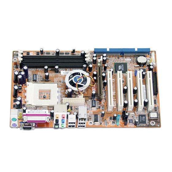
Page 20: Layout Diagram
Chapter 1 1-2. Layout Diagram KD7A... -
Page 21: Chapter 2. Hardware Setup
Hardware Setup Chapter 2. Hardware Setup Before the Installation: Turn off the power supply switch (fully turn off the +5V standby power), or disconnect the power cord before installing or unplugging any connectors or add-on cards. Failing to do so may cause the motherboard components or add-on cards to malfunction or damaged. 2-1. - Page 22 CPU socket. 6. Attach the fan connector of Heatsink & Fan Assembly with the fan connector on the motherboard. ATTENTION: Do not forget to set the correct bus frequency and multiple for your processor. KD7A...
-
Page 23: Install System Memory
Hardware Setup 2-3. Install System Memory This motherboard provides 3 184-pin DDR DIMM sites for memory expansion available from minimum 128MB to maximum 3GB. Table 2-1. Valid Memory Configurations Bank Memory Module Total Memory Bank 0, 1 (DIMM1) 128, 256, 512MB, 1GB 128MB ~ 1GB Bank 2, 3 (DIMM2) 128, 256, 512MB, 1GB... -
Page 24: Connectors, Headers And Switches
Plug in the AC power cord only after you have carefully checked everything. (1). ATX Power Input Connectors This motherboard provides two power connectors to connect to an ATX12V power supply with 300W, 20A +5VDC, and 720mA +5VSB capacity at least. KD7A... -
Page 25: Fan Connectors
Hardware Setup (2). FAN Connectors These 3-pin connectors each provide power to the cooling fans installed in your system. The CPU must be kept cool by using a powerful fan with heatsink. The system is capable of monitoring the speed of the CPU fan. •... -
Page 26: Cmos Memory Clearing Header
Short pin-2 and pin-3 for “Strapping from Hardware” to allow the CPU hardware controls the timing of S2K bus for a better system flexibility. The default setting is pin-1 and pin-2 shorted for “Strapping from boot ROM” to allow the internal boot ROM controls the timing of S2K bus. KD7A... -
Page 27: Wake-Up Header
Hardware Setup (5). Wake-up Header These headers use a jumper cap to enable/disable the wake-up function. • PS2-PWR1: Pin 1-2 shorted (default): Disable wake-up function support at Keyboard/Mouse port. Pin 2-3 shorted: Enable wake-up function support at Keyboard/Mouse port • USB-PWR1: Pin 1-2 shorted (default): Disable wake-up function support at USB1 port. -
Page 28: Front Panel Switches & Indicators Headers
Connects to the Suspend LED cable (if there is one) of chassis front panel. • PWR-ON (Pin 6, 8): Connects to the Power Switch cable of chassis front panel. • PLED (Pin 16, 18, 20): Connects to the Power LED cable of chassis front panel. KD7A... -
Page 29: Additional Usb Port Headers
Hardware Setup (7). Additional USB Port Headers This header provides 2 additional USB 2.0 ports connection through an USB cable designed for USB 2.0 specifications. Pin Assignment Pin Assignment Data0 - Data1 - Data0 + Data1 + Ground Ground User’s Manual... -
Page 30: Front Panel Audio Connection Header
5-6, and pin 9-10 (default setting). Pin Assignment Pin Assignment Audio Mic. Ground Audio Mic. Bias Speaker Out Right Speaker Out Right Channel Channel Return Speaker Out Left Speaker Out Left Channel Channel Return Ground S/PDIF In S/PDIF Out KD7A... -
Page 31: Internal Audio Connectors
Hardware Setup 2-11 (9). Internal Audio Connectors These connectors connect to the audio output of internal CD-ROM drive or add-on card. (10). Accelerated Graphics Port Slot This slot supports an optional AGP graphics card up to AGP 8X mode. Please refer to our Web site for more information on graphics cards. -
Page 32: Floppy Disk Drive Connector
2. Install the other end(s) of ribbon cable into the disk drive connector(s). The colored edge of the ribbon cable should be also aligned with pin-1 of disk drive connector. The endmost connector should be attached to the drive designated as Drive A. KD7A... -
Page 33: Ide Connectors
Hardware Setup 2-13 (12). IDE Connectors This motherboard provides two IDE ports to connect up to four IDE drives at Ultra ATA/100 mode by Ultra ATA/66 ribbon cables. Each cable has 40-pin 80-conductor and three connectors, providing two hard drives connection with motherboard. Connect the single end (blue connector) at the longer length of ribbon cable to the IDE port on motherboard, and the other two ends (gray and black connector) at the shorter length of the ribbon cable to the connectors on hard drives. -
Page 34: Back Panel Connectors
F.L./F.R. (Front Left / Front Right): Connects to the front left and front right channel in the 5.1-channel or regular 2-channel audio system. • LAN: Connects to Local Area Network. • USB1/USB2: Connects to USB devices such as scanner, digital speakers, monitor, mouse, keyboard, hub, digital camera, joystick etc. KD7A... -
Page 35: Chapter 3. Bios Setup
BIOS Setup Chapter 3. BIOS Setup This motherboard provides a programmable EEPROM that you can update the BIOS utility. The BIOS (Basic Input/Output System) is a program that deals with the basic level of communication between processor and peripherals. Use the BIOS Setup program only when installing motherboard, reconfiguring system, or prompted to “Run Setup”. -
Page 36: Softmenu Setup
Chapter 3 3-1. SoftMenu Setup The SoftMenu utility is ABIT’s exclusive and ultimate solution in programming the CPU operating speed. All the parameters regarding CPU FSB speed, multiplier factor, the AGP & PCI clock, and even the CPU core voltage are all available at your fingertips. - Page 37 BIOS Setup Multiplier Factor: This item sets the multiplier factor for the CPU you installed. NOTE: Some processors might have this multiplier factor locked, so there is no way to choose a higher multiplier factor. Power Supply: This option allows you to switch between CPU default and user-defined voltages. Leave this setting to default unless the current CPU type and voltage setting cannot be detected or is not correct.
-
Page 38: Standard Cmos Features
IDE Primary Master / Slave and IDE Secondary Master / Slave: Click <Enter> key to enter its submenu: IDE HDD Auto-Detection: This item allows you to detect the parameters of IDE drives by pressing <Enter> key. The parameters will be shown on the screen automatically. KD7A... - Page 39 BIOS Setup IDE Primary Master / Slave and IDE Secondary Master / Slave: When set to [Auto], the BIOS will automatically check what kind of IDE drive you are using. If you want to define your own drive by yourself, set it to [Manual] and make sure you fully understand the meaning of the parameters.
- Page 40 640K for system with 640K or more memory size installed on the motherboard. Extended Memory: This item displays the amount of extended memory detected during system boot-up. Total Memory: This item displays the total memory available in the system. KD7A...
-
Page 41: Advanced Bios Features
BIOS Setup 3-3. Advanced BIOS Features Hard Disk Boot Priority: This item selects the hard disks booting priority. By pressing <Enter> key, you can enter its submenu where the hard disks detected can be selected for the booting sequence to boot up system. This item functions only when there is the option of [Hard Disk] in any one of the First/Second/Third Boot Device items. - Page 42 1.1. OS Select For DRAM > 64MB: This item allows you to access the memory that is over 64MB in OS/2. Leave this item to its default [Non-OS2] setting for operating system other than OS/2. KD7A...
- Page 43 BIOS Setup Report No FDD For OS: When set to [Enabled], this item allows you to run some older operating system without floppy disk drive. Leave this item to its default setting. Delay IDE Initial (Secs): This item allows the BIOS to support some old or special IDE devices by prolonging this delay time. A larger value will give more delay time to the device for which to initialize and to prepare for activation.
-
Page 44: Advanced Chipset Features
DRAM module does not support the clock you set. When set to [By SPD], the BIOS will read the DRAM module SPD data and automatically set the DRAM clock by the value stored in it. NOTE: This item will be unchangeable at 333MHz FSB. KD7A... - Page 45 BIOS Setup 3-11 DRAM Timing Selectable: Four options are available: Manual By SPD Turbo Ultra. The default setting is By SPD. When set to “By SPD”, the BIOS will read the DRAM module SPD data and automatically set to the values stored in it.
- Page 46 PCI memory address range dedicated for graphics memory address space. AGP Data Transfer Rate: This item selects the data transfer rate of AGP device. A higher rate delivers faster and better graphics to your system. Make sure your graphics card supports the mode you select. KD7A...
- Page 47 BIOS Setup 3-13 AGP Fast Write: Two options are available: Disabled Enabled. The default setting is Disabled. If your AGP adapter can support this function, then you can choose Enabled. Otherwise, choose Disabled. AGP Master 1 WS Write: Two options are available: Disabled Enabled.
- Page 48 PCI Delay Transaction: Two options are available: Disabled or Enabled. The default setting is Enabled. The chipset has an embedded 32-bit posted write buffer to support delay transactions cycles. Select Enabled to support compliance with PCI specification version 2.2. KD7A...
-
Page 49: Integrated Peripherals
BIOS Setup 3-15 3-5. Integrated Peripherals OnChip IDE Device: Click <Enter> key to enter its submenu: IDE Prefetch Mode: Two options are available: Disabled or Enabled. The default setting is Enabled. The onboard IDE drive interfaces supports IDE prefetching for faster drive accesses. If you install a primary and/or secondary add-in IDE interface, set this field to Disabled if the interface does not support prefetching. - Page 50 This item enables or disables the Boot ROM on LAN controller. OnChip USB Controller: This option enables or disables the USB controller. USB Keyboard Support Via: This item allows you to select [BIOS] for using USB keyboard in DOS environment, or [OS] in OS environment. KD7A...
- Page 51 BIOS Setup 3-17 USB Mouse Support Via: This item allows you to select [BIOS] for using USB mouse in DOS environment, or [OS] in OS environment. USB 2.0 Controller: This option enables or disables the USB 2.0 controller. Back to Integrated Peripherals Setup Menu: SuperIO Device: Click <Enter>...
- Page 52 3-18 Chapter 3 [PCI Slot]: When the system boots, it will first initialize PCI. Onboard FDD Controller: Two options are available: Enabled and Disabled. The default setting is Enabled. You can enable or disable the onboard FDD controller. KD7A...
-
Page 53: Power Management Setup
BIOS Setup 3-19 3-6. Power Management Setup ACPI Suspend Type: This item selects the type of Suspend mode. [S1(PowerOn Suspend)]: Enables the Power On Suspend function. [S3(Suspend To RAM)]: Enables the Suspend to RAM function. MODEM Use IRQ: You can specify the IRQ for modem use. Eight options are available: NA 11. - Page 54 Fifteen options are available: Ctrl+F1 ~ Ctrl+F12, Power, Wake and Any Key. The default setting is Ctrl+F1. You can choose the hot key that you want it to turn on your computer power. PS2MS Wakeup: This item controls the PS2 mouse to wake up the system that has been powered down. KD7A...
- Page 55 BIOS Setup 3-21 Resume by OnChip USB: Two options are available: Disabled or Enabled. The default setting is Disabled. When set to Enabled, any event affecting from onchip USB will awaken a system that has powered down. VGA: Two items available: OFF or ON. The default setting is OFF. When set to ON, any event occurring at a VGA port will awaken a system that has powered down.
- Page 56 Two items available: Off or Manual. The default setting is Manual. When you set this item to Manual, the following IRQ events will be available for adjustment. When set to Disabled, activity will neither prevent the system from going into a power management mode nor awaken it. Each item has two options: Enabled Disabled. KD7A...
-
Page 57: Pnp/Pci Configurations
BIOS Setup 3-23 3-7. PnP/PCI Configurations Force Update ESCD: If you want to clear ESCD data next time you boot up, and ask the BIOS to reset the settings for the Plug & Play ISA Card and the PCI Card, select Enabled. But the next time you boot up, this option will automatically be set as Disabled. - Page 58 • If you want to install two PCI cards into those PCI slots that share IRQ with one another at the same time, you must make sure that your OS and PCI devices’ driver supports the IRQ sharing function. KD7A...
-
Page 59: Pc Health Status
BIOS Setup 3-25 3-8. PC Health Status CPU Shutdown Temperature: This item sets the temperature that would shutdown the system automatically in order to prevent system overheats. CPU Warning Temperature: This item selects the CPU’s warning temperature limit. Once the system has detected that the CPU’s temperature exceeded the limit, warning beeps will sound. -
Page 60: Load Fail-Safe Defaults
This option protects the BIOS configuration or restricts access to the computer itself. 3-12. Save & Exit Setup This option saves your selections and exits the BIOS setup menu. 3-13. Exit Without Saving This option exits the BIOS setup menu without saving any change. KD7A... -
Page 61: Appendix A. Install Via 4-In-1 Driver
Install VIA 4-in-1 Driver Appendix A. Install VIA 4-in-1 Driver NOTE: Please install this VIA 4-in-1 driver first after having installed the Windows operating system. The installation procedures and screen shots in this section are based on Windows 2000 operating system. For those of other OS, please follow its on-screen instruction. - Page 62 Appendix A Click [Next]. 7. Choose [Yes, I want to restart my computer now.], and click [OK] to complete setup. KD7A...
-
Page 63: Appendix B. Install Audio Driver
Install Audio Driver Appendix B. Install Audio Driver The installation procedures and screen shots in this section are based on Windows 2000 operating system. For those of other OS, please follow its on-screen instruction. Insert the Driver & Utility CD into CD-ROM drive, it should execute the installation program automatically. - Page 64 Appendix B Appendix B KD7A KD7A...
-
Page 65: Appendix C. Install Lan Driver
Install LAN Driver Appendix C. Install LAN Driver The installation procedures and screen shots in this section are based on Windows 2000 operating system. For those of other OS, please follow its on-screen instruction. Insert the Driver & Utility CD into CD-ROM drive, it should execute the installation program automatically. - Page 66 Appendix C Appendix C KD7A KD7A...
-
Page 67: Appendix D. Install Via Usb 2.0 Driver
Install VIA USB 2.0 Driver Appendix D. Install VIA USB 2.0 Driver NOTE: There is no need to install VIA USB 2.0 driver for the Windows XP operating system with Service Pack 1 already installed. Please run the Windows update for the latest Service Pack. The installation procedures and screen shots in this section are based on Windows 2000 operating system. - Page 68 Appendix D Click [Yes]. Click [OK]. Click [Print to File]. Click [OK]. KD7A...
-
Page 69: Appendix E. Bios Update Guide
BIOS Update Guide Appendix E. BIOS Update Guide The procedure illustrated here is based on the model SE6 as an example; all other models follow the same process. 1. First, find out the model name and version number of this motherboard. You can find a bar-code sticker typed with model name and version number on motherboard PCB. - Page 70 If this “BIOS boot block” remains intact when the BIOS becomes corrupt during programming, then you can boot from a bootable floppy next time you boot your computer. This allows you to flash your BIOS again without the need for technical support from the dealer. KD7A...
-
Page 71: Appendix F. Hardware Monitoring (The Winbond Hardware Doctor Utility
Hardware Monitoring (The Winbond Hardware Doctor Utility) Appendix F. Hardware Monitoring (The Winbond Hardware Doctor Utility) The Winbond Hardware Doctor is a self-diagnostic system for PCs used with Winbond W83627HF chipset. It protects PC hardware by monitoring several critical items including power supply voltages, CPU &... - Page 72 Voltage, Fan Speed, and Temperature readings as well. If any reading is critical or over its limitation, the reading turns red. Also, a pop-up window appears warning you the system has a problem! This is the warning message window: KD7A...
-
Page 73: Appendix G. Troubleshooting (Need Assistance
Troubleshooting (Need Assistance?) Appendix G. Troubleshooting (Need Assistance?) Q & A: Q: Do I need to clear the CMOS before I use a new motherboard to assemble my new computer system? A: Yes, we highly recommend that you clear the CMOS before installing a new motherboard. Please move the CMOS jumper from its default 1-2 position to 2-3 for a few seconds, and then back. - Page 74 Sound Card Driver. Write down the Sound Card model, motherboard model, BIOS identification number on the technical support file (refer to main instructions), and describe the problem in the space provided. We will show you how to fill the “Technical Support Form”. KD7A...
- Page 75 To fill in this “Technical Support Form”, refer to the step-by-step instructions given below: . MODEL: Note the model number given in your user’s manual. Example: KD7A . Motherboard model number (REV): Note the motherboard model number labeled on the motherboard as “REV:*.**”.
-
Page 76: Technical Support Form
Appendix G Technical Support Form Company Name: Phone Number: Contact Person: Fax Number: E-mail Address: Model BIOS ID # Motherboard Model No. DRIVER REV OS/Application Hardware Name Brand Specifications IDE1 IDE2 IDE1 CD-ROM-Drive IDE2 System Memory ADD-ON CARD Problem Description: KD7A... -
Page 77: Appendix H. How To Get Technical Support
Also please make sure you have the latest drivers from your peripheral cards makers! 3. Check the ABIT Technical Terms Guide and FAQ on our Website. We are trying to expand and make the FAQs more helpful and information rich. Let us know if you have any suggestions. - Page 78 They should have reasonable return or refund policies. How they serve you is also a good reference for your next purchase. 6. Contacting ABIT. If you feel that you need to contact ABIT directly you can send email to the ABIT technical support department. First, please contact the support team for the branch office closest to you.
- Page 79 How to Get Technical Support North America and South America: Japan: ABIT Computer (U.S.A.) Corporation ABIT Computer (Japan) Co. Ltd. 45531 Northport Loop West, Fax: 81-3-5396-5110 Fremont, California 94538, U.S.A. http://www.abit4u.jp Tel: 1-510-623-0500 Fax: 1-510-623-1092 Shanghai: sales@abit-usa.com ABIT Computer (Shanghai) Co. Ltd.
- Page 80 Please contact the reseller from whom you bought the product. You should be able to get RMA service there. 8. Reporting Compatibility Problems to ABIT. Because of tremendous number of email messages we receive every day, we are forced to give greater weight to certain types of messages than to others.
Need help?
Do you have a question about the KD7A and is the answer not in the manual?
Questions and answers