
Subscribe to Our Youtube Channel
Related Manuals for Abit KW7-G


Summary of Contents for Abit KW7-G
- Page 1 KW7 Series (KW7, KW7-G) AMD Athlon XP System Board Socket 462 User’s Manual 4200-0416-02 Rev. 1.01...
- Page 2 Copyright and Warranty Notice The information in this document is subject to change without notice and does not represent a commitment on part of the vendor, who assumes no liability or responsibility for any errors that may appear in this manual. No warranty or representation, either expressed or implied, is made with respect to the quality, accuracy or fitness for any particular part of this document.
-
Page 3: Table Of Contents
Table of Contents Chapter 1. Introduction ................1-1 1-1. Features & Specifications ................1-1 1-2. Layout Diagram ..................1-3 Chapter 2. Hardware Setup..............2-1 2-1. Install The Motherboard................2-1 2-2. Install CPU and Heatsink.................2-1 2-3. Install System Memory ................2-3 2-4. Connectors, Headers and Switches ............2-5 (1). - Page 4 Appendix D. Install VIA USB 2.0 Driver .............D-1 Appendix E. Install Serial ATA RAID Driver............E-1 Appendix F. ABIT EQ (The Hardware Doctor Utility) ........F-1 Appendix G. FlashMenu (BIOS Update Utility) ..........G-1 Appendix H. Troubleshooting (Need Assistance?)..........H-1 Appendix I.
-
Page 5: Chapter 1. Introduction
• 2 channels of Serial ATA 150MB/s data transfer rate with RAID function (0/1) via South Bridge 5. IEEE 1394 • Supports 2-Port IEEE 1394 at 100/200/400 Mb/s transfer rate (KW7-G) 6. LAN • Onboard 10/100/1000M LAN Controller (KW7-G) •... - Page 6 • 1x AUDIO1 connector (Rear-Left / Rear-Right, Center/Subwoofer) • 1x AUDIO2 connector (Mic-In, Line-In, Front-Left/Front-Right) • 2x USB 2.0 connectors, 1x IEEE 1394 connector (KW7-G) • 2x USB 2.0 connectors, 1x RJ-45 LAN connector 11. Miscellaneous • ATX form factor (305mm x 245mm) •...
-
Page 7: Layout Diagram
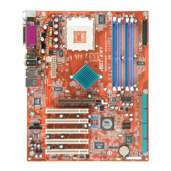
Introduction 1-2. Layout Diagram User’s Manual... - Page 8 Chapter 1 KW7 Series...
-
Page 9: Chapter 2. Hardware Setup
Hardware Setup Chapter 2. Hardware Setup Before the Installation: Turn off the power supply switch (fully turn off the +5V standby power), or disconnect the power cord before installing or unplugging any connectors or add-on cards. Failing to do so may cause the motherboard components or add-on cards to malfunction or damaged. 2-1. - Page 10 Chapter 2 This motherboard provides a ZIF (Zero Insertion Force) Socket 462 to install AMD Socket A CPU. The CPU you bought should have a kit of heatsink and cooling fan along with. If that’s not the case, buy one specially designed for Socket A. Please refer to the figure shown here to install CPU and heatsink.
-
Page 11: Install System Memory
Hardware Setup 2-3. Install System Memory This motherboard provides four 184-pin DDR DIMM slots for Dual Channel DDR 266/333/400 memory modules with memory expansion size up to 4GB. To reach the performance of Dual Channel DDR, the following rules must be obeyed: •... - Page 12 Chapter 2 Power off the computer and unplug the AC power cord before installing or removing memory modules. 1. Locate the DIMM slot on the board. 2. Hold two edges of the DIMM module carefully, keep away touching connectors. 3. Align the notch key on the module with the rib on the slot.
-
Page 13: Connectors, Headers And Switches
Hardware Setup 2-4. Connectors, Headers and Switches Here we will show you all of the connectors, headers and switches, and how to connect them. Please read the entire section for necessary information before attempting to finish all the hardware installation inside the computer chassis. -
Page 14: Fan Connectors
Chapter 2 (2). FAN Connectors These 3-pin connectors each provide power to the cooling fans installed in your system. The CPU must be kept cool by using a powerful fan with heatsink. The system is capable of monitoring the speed of the CPU fan. •... -
Page 15: Cmos Memory Clearing Header
Hardware Setup (3). CMOS Memory Clearing Header This header uses a jumper cap to clear the CMOS memory. • Pin 1-2 shorted (default): Normal operation. • Pin 2-3 shorted: Clear CMOS memory. WARNING: Turn the power off first (including the +5V standby power) before clearing the CMOS memory. -
Page 16: S2K Mode Select Header
Chapter 2 (4). S2K Mode Select Header This header uses a jumper to select the S2K mode. Short pin-2 and pin-3 for “Strapping from Hardware” to allow the CPU hardware controls the timing of S2K bus for a better system flexibility. The default setting is pin-1 and pin-2 shorted for “Strapping from boot ROM”... -
Page 17: Wake-Up Header
Hardware Setup (5). Wake-up Header These headers use a jumper cap to enable/disable the wake-up function. • PS2-PWR1: Pin 1-2 shorted (default): Disable wake-up function support at Keyboard/Mouse port. Pin 2-3 shorted: Enable wake-up function support at Keyboard/Mouse port • USB-PWR1: Pin 1-2 shorted (default): Disable wake-up function support at USB1 port. -
Page 18: Front Panel Switches & Indicators Headers
2-10 Chapter 2 (6). Front Panel Switches & Indicators Headers This header is used for connecting switches and LED indicators on the chassis front panel. Watch the power LED pin position and orientation. The mark “+” align to the pin in the figure below stands for positive polarity for the LED connection. -
Page 19: Additional Ieee1394 Port Headers
Hardware Setup 2-11 (7). Additional IEEE1394 Port Headers This header each provides one additional IEEE1394 port connection through an extension cable and bracket. Pin Assignment Pin Assignment TPA0 + TPA0 - Ground Ground TPB0 + TPB0 - +12V +12V Ground (8). -
Page 20: Front Panel Audio Connection Header
2-12 Chapter 2 (9). Front Panel Audio Connection Header This header provides the connection to audio connector at front panel. • To use the audio connector at front panel, remove all the jumpers on this header, and then connect to front panel by the extenson cable provided with the chassis. •... -
Page 21: Internal Audio Connectors
Hardware Setup 2-13 (10). Internal Audio Connectors These connectors connect to the audio output of internal CD-ROM drive or add-on card. (11). Accelerated Graphics Port Slot This slot supports an optional AGP graphics card up to AGP 8X mode. ATTENTION: This motherboard does not support 3.3V AGP cards. Use only 1.5V or 0.8V AGP cards. User’s Manual... -
Page 22: Floppy And Ide Disk Drive Connectors
2-14 Chapter 2 (12). Floppy and IDE Disk Drive Connectors The FDC1 connector connects up to two floppy drives with a 34-wire, 2-connector floppy cable. Connect the single end at the longer length of ribbon cable to the FDC1 on the board, the two connectors on the other end to the floppy disk drives connector. -
Page 23: Serial Ata Connectors
Hardware Setup 2-15 (13). Serial ATA Connectors These connectors are provided to attach one Serial ATA device at each channel via Serial ATA cable. A RAID 0 or RAID 1 array is also available by software configuration. To enable the SATA1 and SATA2 controller, the item “OnChip SATA Device” must be kept enabled (default setting) in the BIOS menu of “OnChip IDE Device”. -
Page 24: Back Panel Connectors
F.L./F.R. (Front Left / Front Right): Connects to the front left and front right channel in the 5.1-channel or regular 2-channel audio system. • IEEE1394: Connects to devices of IEEE1394 protocol. (For KW7-G only) • LAN: Connects to Local Area Network. -
Page 25: Chapter 3. Bios Setup
BIOS Setup Chapter 3. BIOS Setup This motherboard provides a programmable EEPROM that you can update the BIOS utility. The BIOS (Basic Input/Output System) is a program that deals with the basic level of communication between processor and peripherals. Use the BIOS Setup program only when installing motherboard, reconfiguring system, or prompted to “Run Setup”. -
Page 26: Softmenu Setup
Chapter 3 3-1. SoftMenu Setup The SoftMenu utility is ABIT’s exclusive and ultimate solution in programming the CPU operating speed. All the parameters regarding CPU FSB speed, multiplier factor, the AGP & PCI clock, and even the CPU core voltage are all available at your fingertips. - Page 27 BIOS Setup Power Supply: This option allows you to switch between CPU default and user-defined voltages. Leave this setting to default unless the current CPU type and voltage setting cannot be detected or is not correct. The option “User Define” enables you to select the Core Voltage manually. CPU Core Voltage: This item selects the CPU core voltage.
-
Page 28: Standard Cmos Features
Chapter 3 3-2. Standard CMOS Features This section contains the basic configuration parameters of the BIOS. These parameters include date, hour, VGA card, FDD and HDD settings. Phoenix – AwardBIOS CMOS Setup Utility Standard CMOS Features Date (mm:dd:yy) Sun. Aug 22 2004 Item Help Time (hh:mm:ss) 12 : 34 : 56... - Page 29 BIOS Setup IDE Primary Master/Slave, IDE Secondary Master/Slave: Click <Enter> key to enter its submenu: Phoenix – AwardBIOS CMOS Setup Utility IDE Primary Master IDE HDD Auto-Detection [Press Enter] Item Help IDE Primary Master [Auto] - Access Mode [Auto] Capacity 0 MB Cylinder Head...
- Page 30 Chapter 3 Head: This item configures the numbers of read/write heads. Precomp: This item displays the number of cylinders at which to change the write timing. Landing Zone: This item displays the number of cylinders specified as the landing zone for the read/write heads. Sector: This item configures the numbers of sectors per track.
-
Page 31: Advanced Bios Features
BIOS Setup 3-3. Advanced BIOS Features Phoenix – AwardBIOS CMOS Setup Utility Advanced BIOS Features ► Hard Disk Boot Priority [Press Enter] Item Help First Boot Device [Floppy] Second Boot Device [Hard Disk] Third Boot Device [CDROM] Boot Other Device [Enabled] Swap Floppy Drive [Disabled]... - Page 32 Chapter 3 Typematic Rate Setting: This item allows you to adjust the keystroke repeat rate. When set to Enabled, you can set the two keyboard typematic controls that follow (Typematic Rate and Typematic Rate Delay). If this item is set to Disabled, the BIOS will use the default setting.
-
Page 33: Advanced Chipset Features
BIOS Setup 3-4. Advanced Chipset Features Phoenix – AwardBIOS CMOS Setup Utility Advanced Chipset Features ► DRAM Clock/Drive Control [Press Enter] Item Help ► AGP & P2P Bridge Control [Press Enter] ► CPU & PCI Bus Control [Press Enter] Memory Hole At 15-16M [Disabled] Top Performance [Disabled]... - Page 34 3-10 Chapter 3 DRAM Clock/Drive Control: Click <Enter> key to enter its submenu: Phoenix – AwardBIOS CMOS Setup Utility DRAM Clock/Drive Control Current FSB Frequency 166 MHz Item Help Current DRAM Frequency 133 MHz DRAM Clock [By SPD] DRAM Timing Selectable [By SPD] X - CAS Latency Time X - Bank Interleave...
- Page 35 BIOS Setup 3-11 DRAM Clock: This item sets the DRAM clock of your DRAM module. The system may be unstable or unable to boot up if your DRAM module does not support the clock you set. When set to [By SPD], the BIOS will read the DRAM module SPD data and automatically set the DRAM clock by the value stored in it.
- Page 36 3-12 Chapter 3 Ch. B MD Output Delay DQS/DQM/CS/CKE/MAx Drive: Two options are available: [Auto] or [Manual]. The following items will be available to make adjustments by selecting option [Manual]. RxE0 Ch. A DQS Drive RxE1 Ch. B DQS Drive RxE2 Ch.
- Page 37 BIOS Setup 3-13 AGP & P2P Bridge Control: Click <Enter> key to enter its submenu: Phoenix – AwardBIOS CMOS Setup Utility AGP & P2P Bridge Control CPU to AGP Post Write [Enabled] Item Help AGP Aperture Size [128M] AGP 2.0 Mode [4X] AGP Driving Control [Auto]...
- Page 38 3-14 Chapter 3 AGP Master 1 WS Write: Two options are available: Disabled Enabled. The default setting is Disabled. This implements a single delay when writing to the AGP Bus. When you set it to Enabled, two-wait states are used by the system, allowing for greater stability.
- Page 39 BIOS Setup 3-15 CPU to PCI Post Write Two options are available: Enabled or Disabled. The default is Enabled, When Enable, data transmission from CPU to PCI bus are buffered and compensate for the different speed between CPU and PCI bus. If it is set to Disabled, data transmissions are not buffered and CPU must wait until the data transmission is complete and then start another transmission cycle.
-
Page 40: Integrated Peripherals
3-16 Chapter 3 3-5. Integrated Peripherals Phoenix – AwardBIOS CMOS Setup Utility Integrated Peripherals ► OnChip IDE Device [Press Enter] Item Help ► OnChip PCI Device [Press Enter] ► SuperIO Device [Press Enter] Init Display First [PCI Slot] Onboard Lan Controller [Disabled] Onboard IEEE1394 Controller [Disabled]... - Page 41 BIOS Setup 3-17 IDE Prefetch Mode: Two options are available: Disabled or Enabled. The default setting is Enabled. The onboard IDE drive interfaces supports IDE prefetching for faster drive accesses. If you install a primary and/or secondary add-in IDE interface, set this field to Disabled if the interface does not support prefetching. SATA Mode: This item determines the mode for on-chip Serial ATA.
-
Page 42: Superio Device
3-18 Chapter 3 USB Keyboard Support: This item allows you to select [BIOS] for using USB keyboard in DOS environment, or [OS] in OS environment. USB Mouse Support: This item allows you to select [BIOS] for using USB mouse in DOS environment, or [OS] in OS environment. - Page 43 BIOS Setup 3-19 KB Power On Password: When you perss the <Enter> key, then you can enter the password you want. When set be done, you need to saving and leave the BIOS setting menu to reboot your computer system. Next time when you shutdown your computer, you can’t use the power button to turn on the computer power anymore.
- Page 44 3-20 Chapter 3 Game Port Address: Three options are available: Disabled 209. The default setting is 201. This item sets the address of the onboard game port connector. Midi Port Address: Four options are available: Disabled 290. The default setting is 330. This item sets the address of the onboard midi port connector.
-
Page 45: Power Management Setup
BIOS Setup 3-21 3-6. Power Management Setup Phoenix – AwardBIOS CMOS Setup Utility Power Management Setup ACPI Suspend Type [S1(POS)] Item Help MODEM Use IRQ [NA] Power Button Function [Instant-Off] Run VGABIOS if S3 Resume [Auto] ► IRQ/Event Activity Detect [Press Enter] ↑↓:Move Enter:Select +/-/PU/PD:Value F10:Save ESC:Exit F1:General Help F5: Previous Values... - Page 46 3-22 Chapter 3 IRQ/Event Activity Detect: Click <Enter> key to enter its submenu: Phoenix – AwardBIOS CMOS Setup Utility IRQ/Event Activity Detect Power On Function [Button Only] Item Help X - Hot Key Power On Ctrl-F1 X - KB Power On Password Press Enter X - PS2 Mouse Wakeup Disbaled...
- Page 47 BIOS Setup 3-23 PS2 Mouse Wakeup: This item controls the PS2 mouse to wake up the system that has been powered down. Resume by OnChip USB: Two options are available: Disabled or Enabled. The default setting is Disabled. When set to Enabled, any event affecting from onchip USB will awaken a system that has powered down.
-
Page 48: Pnp/Pci Configurations
3-24 Chapter 3 3-7. PnP/PCI Configurations Phoenix – AwardBIOS CMOS Setup Utility PnP/PCI Configurations Resources Controlled By [Auto] Item Help x IRQ Resources Press Enter PCI/VGA Pallete Snoop [Disbaled] Allocate IRQ to Video [Enabled] Allocate IRQ to USB [Enabled] PIRQ_0 Use IRQ No. [Auto] PIRQ_1 Use IRQ No. -
Page 49: Pc Health Status
BIOS Setup 3-25 Allocate IRQ To USB: This item assigns an IRQ for the USB device connected. [Enabled]: Automatically assign an IRQ for the USB device connected. [Disabled]: The IRQ that was previously occupied by the USB device connected will be available for new device. -
Page 50: Load Fail-Safe Defaults
3-26 Chapter 3 All Voltages, Fans Speed and Thermal Monitoring: These unchangeable items list the current status of the CPU and environment temperatures, fan speeds, and system power voltage. NOTE: The hardware monitoring features for temperatures, fans and voltages will occupy the I/O address from 294H to 297H. -
Page 51: Appendix A. Install Via 4-In-1 Driver
Install VIA 4-in-1 Driver Appendix A. Install VIA 4-in-1 Driver NOTE: Please install this VIA 4-in-1 driver first after having installed the Windows operating system. The installation procedures and screen shots in this section are based on Windows XP operating system. - Page 52 Appendix A Click [Next]. 7. Choose [Yes, I want to restart my computer now.], and click [OK] to complete setup. KW7 Series...
-
Page 53: Appendix B. Install Audio Driver
Install Audio Driver Appendix B. Install Audio Driver The installation procedures and screen shots in this section are based on Windows XP operating system. For those of other OS, please follow its on-screen instruction. Insert the Driver & Utility CD into CD-ROM drive, it should execute the installation program automatically. - Page 54 Appendix B Appendix B KW7 Series KW7 Series...
-
Page 55: Appendix C. Install Lan Driver
Install LAN Driver Appendix C. Install LAN Driver The installation procedures and screen shots in this section are based on Windows XP operating system. For those of other OS, please follow its on-screen instruction. Insert the Driver & Utility CD into CD-ROM drive, it should execute the installation program automatically. - Page 56 Appendix C Appendix C KW7 Series KW7 Series...
-
Page 57: Appendix D. Install Via Usb 2.0 Driver
Install VIA USB 2.0 Driver Appendix D. Install VIA USB 2.0 Driver NOTE: This VIA USB 2.0 driver package requires Windows XP SP1 (Service Pack 1), Windows 2000 SP4, or system upgrade through Windows Update. The installation procedures and screen shots in this section are based on Windows XP operating system. - Page 58 Appendix D Appendix D KW7 Series KW7 Series...
-
Page 59: Appendix E. Install Serial Ata Raid Driver
Install Serial ATA RAID Driver Appendix E. Install Serial ATA RAID Driver The installation procedures and screen shots in this section are based on Windows XP operating system. For those of other OS, please follow its on-screen instruction. Insert the Driver & Utility CD into CD-ROM drive, it should execute the installation program automatically. - Page 60 Appendix E 6. Choose [Yes, I want to restart my computer now.], and click [Finish] to complete setup. KW7 Series...
-
Page 61: Appendix F. Abit Eq (The Hardware Doctor Utility
ABIT EQ (The Hardware Doctor Utility) Appendix F. ABIT EQ (The Hardware Doctor Utility) The installation procedures and screen shots in this section are based on Windows XP operating system. For those of other OS, please follow its on-screen instruction. - Page 62 Appendix F 6. This screen appears. ABIT EQ shows you the status of Voltage, Fan Speed, and Temperature readings as well. (The item names in this screen shot are for reference only, may not be exactly the same as what you see on your monitor.)
-
Page 63: Appendix G. Flashmenu (Bios Update Utility
If not, double-click the execution file at the main directory of this CD to enter the installation menu. After entering the installation menu, move your curser to [ABIT Utility] tab. Click [FlashMenu]. The following screen appears. Click [Next]. 1. Click [Next]. - Page 64 Appendix G Click [OK]. 7. This FlashMenu screen appears. You can easily update the BIOS from clicking [Update From File], [One Click LiveUpdate], or [LiveUpdate Step by Step] button. KW7 Series...
-
Page 65: Appendix H. Troubleshooting (Need Assistance
Troubleshooting (Need Assistance?) Appendix H. Troubleshooting (Need Assistance?) Q & A: Q: Do I need to clear the CMOS before I use a new motherboard to assemble my new computer system? A: Yes, we highly recommend that you clear the CMOS before installing a new motherboard. Please move the CMOS jumper from its default 1-2 position to 2-3 for a few seconds, and then back. - Page 66 Appendix H Q: How can I get a quick response to my request for technical support? A: Be sure to follow the guidelines as stated in the “Technical Support Form” section of this manual. If you have a problem during operation, in order to help our technical support personnel quickly determine the problem with your motherboard and give you the answers you need, before filling in the technical support form, eliminate any peripheral that is not related to the problem, and indicate it on the form.
- Page 67 To fill in this “Technical Support Form”, refer to the step-by-step instructions given below: . MODEL: Note the model number given in your user’s manual. Example: KW7, KW7-G . Motherboard model number (REV): Note the motherboard model number labeled on the motherboard as “REV:*.**”.
-
Page 68: Technical Support Form
Appendix H Technical Support Form Company Name: Phone Number: Contact Person: Fax Number: E-mail Address: Model BIOS ID # Motherboard Model No. DRIVER REV OS/Application Hardware Name Brand Specifications IDE1 IDE2 IDE1 CD-ROM-Drive IDE2 System Memory ADD-ON CARD Problem Description: KW7 Series... -
Page 69: Appendix I. How To Get Technical Support
Also please make sure you have the latest drivers from your peripheral cards makers! 3. Check the ABIT Technical Terms Guide and FAQ on our Website. We are trying to expand and make the FAQs more helpful and information rich. Let us know if you have any suggestions. - Page 70 They should have reasonable return or refund policies. How they serve you is also a good reference for your next purchase. 6. Contacting ABIT. If you feel that you need to contact ABIT directly you can send email to the ABIT technical support department. First, please contact the support team for the branch office closest to you.
- Page 71 Unit 3, 24-26 Boulton Road, Stevenage, Herts SG1 4QX, UK Tel: 44-1438-228888 Fax: 44-1438-226333 E-mail: sales@abitcomputer.co.uk Germany and Benelux (Belgium, AMOR Computer B.V. (ABIT's European Office) Jan van Riebeeckweg 15, 5928LG, Venlo, Netherlands, Luxembourg), The Netherlands France, Italy, Spain, Portugal, Greece, Denmark, Norway, Tel: 31-77-3204428...
- Page 72 Web Site: http://www.abit.com.tw 8. Reporting Compatibility Problems to ABIT. Because of tremendous number of email messages we receive every day, we are forced to give greater weight to certain types of messages than to others. For this reason, any compatibility problem that is reported to us, giving detailed system configuration information and error symptoms will receive the highest priority.
Need help?
Do you have a question about the KW7-G and is the answer not in the manual?
Questions and answers