Table of Contents
Advertisement
OPERATORS MANUAL
U
rsal
MARINE DIESEL ENGINES
M3-20B M-25XPB M-35B
-
.
- ... B
-50B
PUBLICATION 200550
REVISION
2
FEBRUARY 2010
WE5TERBEKE CORPORATION. MYLES STANDISH INDUSTRIAL PARK
150JOHN HANCOCK ROAD, TAUNTON, MA 02780·7319 U.S.A. .
TEl..: (508)823-7871
0
FAX: (508}B84·9688· weBSITE: WWW.WESTERBEIfE.COM
..4JJs!J
Member
NaluJlla[
Marille Manu/acturers Associalioll
Advertisement
Table of Contents
Troubleshooting

Related Manuals for Westerbeke Universal M3-20B


Summary of Contents for Westerbeke Universal M3-20B
- Page 1 OPERATORS MANUAL rsal MARINE DIESEL ENGINES M3-20B M-25XPB M-35B - ... B -50B PUBLICATION 200550 REVISION FEBRUARY 2010 WE5TERBEKE CORPORATION. MYLES STANDISH INDUSTRIAL PARK 150JOHN HANCOCK ROAD, TAUNTON, MA 02780·7319 U.S.A. . TEl..: (508)823-7871 FAX: (508}B84·9688· weBSITE: WWW.WESTERBEIfE.COM ..4JJs!J Member...
- Page 2 Shut dllwn the unit and do not restart until It been inspected and repaired. A WARNING DECAL is provided by WESTERBEKE and should be fixed to a bulkhead near your engine or generator. WESTERBEKE also recommends installing CARBON MONOXIDE DETECTORS In the ~!-!~~lII!Ii!i!IlI!"~~\...
- Page 3 SAFETY INSTRUCTIONS PREVENT BURNS - FIRE Read this safety manual carefully. Most accidents are WARNING: caused by failure to follow fundamental rules and precau· Flro can cause injury or death! tions. Know when dangerous conditions exist and take the necessary precautions to protect yourself, your personnel, •...
- Page 4 SAFETY INSTRUCTIONS TOXIC EXHAUST GASES ACCIDENTAl STARTING WARNING: cause Accldtmtal stalflng can In/ury WARNING: Carbon monoxide (CO) Is deadly gas! tItNIth! • Ensure that the exhaust system is adequate to expel gases • Disconnect the battery cables before servicing the engine/ discharged from the engine.
- Page 5 SAFETY INSTRUCTIONS ABYC, NFPA AND USCG PUBLICATIONS FOR • Do not wear loose clothing or jewelry when servicing equipment; tie back long hair and avoid wearing loose INSTAlLING DIESEL ENGINES jackets, shirts, sleeves, rings, necklaces or bracelets that Read the following ABYC, NFPA and USCG publications could be caught in moving parts.
- Page 6 INSTALLATION When installing WESTERBEKE engines and generators it is important that strict attention be paid to the following information: CODES AND REGULATIONS Strict federal regulations, ABYC guidelines, and safety codes must be complied with when installing engines and generators in a marine environment.
-
Page 7: Table Of Contents
TABLE OF CONTENTS Parts Identification ............Wiring Schematic (Catalina) ......... Introduction ..............Engine Adjustments ............Throttle and Stop Assembly ........27 Warranty Procedures ............ Valve Clearance ............27 Serial Number Location ..........3 Testing Engine Compression ........28 Admiral Control Panel ............. Testing Oil Pressure ........... -
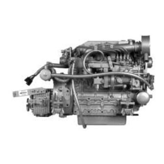
Page 8: Parts Identification
PARTS IDENTIFICATION MANIFOLO'p'R.E.SSUI~E C,~P FILL ICOOLANT THERMOSTAT ASSEMBLY M-40BILLUSTRATED =::;>F\-\---j\lR FIlTER SILENCER ~~~~:d "\l!i-of-----OIL DRAIN HOSE ALTERNATOR REAR RIGHT SIDE .u«"'r-~ COOLANT PUMP PREHEAT SOLENOID OIL PAN COOLANT DRAIN PRESSURE CAP / MA."ULU FILL] 1.0. NAME PLATE FUEL PUMP START PUMP-~--->j1U1i MOTOR COOLANT... -
Page 9: Introduction
BE LIABLE FOR ANY TYPE OF DAMAGE OR INJURY throughout. An extensive network of UNIVERSAL INCURRED IN CONNECTION WITH OR ARISING OUT WESTERBEKE distributors, dealers and service centers are OF THE FURNISHING OR USE OF SUCH SOFTWARE. available worldwide. Should your engine require servicing, contact your nearest dealer for assistance. - Page 10 SPARES AND ACCESSORIES. Certain spares will be needed to support and maintain your UNIVERSAL marine engine. Your UNlVERSAU WESTERBEKE dealer will assist you in preparing an on IllJERSTANDING THE DIESEL ENGINE board inventory of spare parts. See the UNIVERSAL SPARE PARTS page in this manual for a suggested list.
-
Page 11: Admiral Control Panel
ADMIRAL CONTROL PANEL UNIVERSAL offers two optional panels. Refer to the When the engine is shut down with the Key Switch turned instruction page that applies to the panel you purchased. off, the water temperature gauge will continue to register the last temperature reading indicated by the gauge before elec- ADMIRAL PANn trical power was turned off. -
Page 12: Captain Control Panel
CAPTAIN CONTROL PANEL and one for high ENGINE COOLANT TEMPERATURE. It CAPTAIN PANEL also includes an alarm buzzer for low on.. PRESSURE or This manually-operated control panel is equipped with a Key high WA1ER TEMPERATURE. The RPM gauge is illumi- Switch, an RPM gauge, PREHEAT and START buttons, an nated when the Key Switch is turned on and remains illumi- INSTRUMENT TEST button and three indicator lamps, one... -
Page 13: Diesel Fuel, Engine Oil And Engine Coolant
MAINTENANCE SCHEDULE A coolant recovery tank kit is supplied with each Westerbeke Corporation does not approve or disapprove UNIVERSAL diesel engine. The purpose of this recovery the use of synthetic oils. If synthetic oils are used, engine tank is to allow for engine coolant expansion and contraction break-in must be performed using conventional oil. -
Page 14: Preparations For Initial Start-Up
PREPARATIONS FOR INITIAL START-UP PREST ART INSPECTION Check the DC electrical system. Inspect wire connections and battery cable connections. Before starting your engine for the first time or after a pro- Visually examine the unit. Look for loose or missing longed layoff - check the following items. -
Page 15: Startlngjstopplng Procedure
STARTING/STOPPING PROCEDURE STARTING PROCEDURE CAUTION: Prolonged cranking intervals without Place the transmission in neutral and advance the throttle control slightly open. the engine starting can result in the engine exhaust system filling with raw water. This may happen because CAUTION: the pump is pumping raw water through the raw water Make certain the transmission is in 1IIIIIIrBI. -
Page 16: Break-In Procedure
CRUISE MODEL IDLE MAXIMUM Perform this conditioning carefully, keeping in mind the following: M3-20B 1000 -1200 2500 - 3000 3500 - 3600 Start the engine according to the Starting Procedure M25XPB 1000 -1200... -
Page 17: The Dall, Routine
THE DAILY ROUTINE CHECK LIST START YOUR ENGINE NOTE: Each day before starting your engine, take a few moments to STARTING STOPPING PROCEDURE in this run this check list: manual for more detailed instructions. Visually inspect the engine for fuel, oil, coolant and Put transmission in neutral, throttle advanced. -
Page 18: Maintenance Schedule
MAINTENANCE SCHEDULE WARNING: Never attempt to pertonn any service whIle the engine is runnIng. Wear the proper safety equIpment such as goggles and gloves, and use the correct tools tor each Job. DIsconnect the battery tennlnals when servIcIng any of the engIne's DC electrical equIpment. NOTE: Many of the following maintenance jobs are simple but others are more difficult... - Page 19 MAINTENANCE SCHEDULE NOTE: Use the engine hour meter gauge to log your engine hours or record your engine hours by running time. CHECK HOURS OF OPERATION SCHEDULED EACH EXPLANATION OF SCHEDULED MAINTENANCE 500 750 1000 1250 MAINTENANCE Engine Hoses Hose should be hard & tight Replace if soft or spongy.
-
Page 20: Engine Cooling Clrcuil
ENGINE COOLING CIRCUIT Drain the engine coolant by loosening the drain plug on the DESCRIPTION engine block and opening the manifold pressure cap. Flush The engine is fresh water cooled (engine coolant) by an the system with fresh water, then start the refill process. See engine-mounted heat exchanger. -
Page 21: Raw Water Pump
ENGINE COOLING CIRCUIT RAW WATER CODLING CIRCUIT 7. Check the cam and inner wear plate for wear. Replace as needed. The raw water flow is created by a positive displacement impeller pump. This pump draws water directly from the ocean, lake, or river from a through-hull opening through a CAUTION: If any of the vanes have broken off the hose to the water strainer. -
Page 22: Raw Water Intake Strainer
ENGINE COOLING CIRCUIT HEAT EXCHANGER THERMOSTAT A \hennostat, located near the manifold at the front of the engine, controls the coolant temperature as it continuously flows through the closed cooling circuit. When the engine is flTSt started the closed thennostat prevents coolant from flow- ing (some coolant is by-passed through a hole in the thenno- stat to prevent the exhaust manifold from overheating). -
Page 23: Engine 011 Change
ENGINE OIL CHANGE DRAIN THE SUMP Replacing the Oil Filter The engine oil should be warm. Remove the oil drain hose When removing the used oil filter, you may find it helpful from its attachment bracket and lower it into a container and and cleaner to punch a hole in the upper and lower portion of allow the oil to drain, or attach a pump to the end of the drain the old filter to drain the oil from it into a container before... -
Page 24: Remote 011 Filter
REMOTE OIL FILTER (OPTIONAL KIT PN #040078 INSTALLATION NOTE: Westerbeke is not respollSible for ellgine failure due to incorrect installation the Remote Oil Filter. This popular accessory is used to relocate the engine's oil filter from the engine to a more convenient location such as... -
Page 25: Fuel S,Stem
FUEL SYSTEM FUEL ADDITIVES FUEL RETURN LINE SHUT-OFF VALVE IM-SOBl fungus or bacteria is causing fuel problems, you should A shut-off valve is located on the fuel retum line near the have an authorized dealer correct these problems. Then use injection pump. -
Page 26: Fuel Filters
FUEL SYSTEM FUEL WATER SEPARATOR AWARNING: Shut off tho fuel valvo at tho tank whlln A primary fuel filter of the water separating type must be SBtrlclng tho fU1I1 system. Tako calo In catching any fulll installed between the fuel tank and the engine to remove that may spill. -
Page 27: Dc Electrical Srstem
DC ELECTRICAL SYSTEM ENGINE 12 VOLT DC CONTROL CIRCUIT GLOW PLUGS The engine has a 12 volt DC electrical control circuit that is The glow plugs are wired through the preheat solenoid. shown on the wiring diagrams that follow. Refer to these dia- When PREHEAT is pressed at the control panel this solenoid grams when troubleshooting or when servicing the DC elec- should "click"... -
Page 28: Alternator Troubleshooting
DC ELECTRICAL SYSTEM DESCRIPTION WARNING: Before stattlng the engine make cettain The charging system consists of an alternator with a mounted that everyone is clear of moving Keep away from paris! voltage regulator, an engine DC wiring harness, a mounted test sheallBS and belts during procedures. -
Page 29: Wiring Diagram
DC ELECTRICAL SYSTEM WIRING DIAGRAM #39144 These diagrams illustrate the 12 volt negative ground electrical circuit. The two oplionallnslrumenl panels, the CAPTAIN PANEL and the ADMIRAL PANEL are diagramed below. When an ADMIRAL PANEL Is Installed, two additional Instrument sendors are assembled 10 the engine to provide data lor the panel gauges (refer to the iIIustra·... -
Page 30: Wiring Schematic
DC ELECTRICAL SYSTEM WIRING SCHEMATIC #39144 12 yOt ~Ol. ITARlU _----------- L._ " U(HUT -I SOl. UQI'LUU L _ _ AU(UUO. :Gi'\ ~91l': ". c .•• ' U II' 'UlL $~L.B- ~.!.'!..!. " • " ,Mi:~~ " · •. t.,;:;' •... -
Page 31: Wiring Diagram (Catalina)
WIRING DIAGRAM CATALINA YACHTS #200360 PREHEAT __ , I~,..j~ SOl EMO I LIFT PIIMPS BATTERY SWITCH* - ':i}---f---<D CIRCUlI BREAKER An on·oll swllch should be inslalled between Ihe ballery and the starter to dlsconnecllhe baHery In an emergency and when leaving Ihe boal. A switch wllh a conlinuous raling 01 •... -
Page 32: Wiring Schematic (Catalina)
WIRING SCHEMATIC CATALINA YACHTS #200360 ST RTE R SOLENOID r---l STARTER L ___ J PREHEAT SOLENOID r---l GLOWPLUGS L ___ J RESISTOR IIZW AL TERNATOR OUTPUT " " "" <r-r. a.:~ ~~I( " " 1"10 "101 <, . . 1< .L-f-l lol- -:::>... -
Page 33: Engine Adjustments
1·3-4-2 CYLINDER MODELS Adjust the valves beginning with Cylinder #1. Rotate the MOOEL M3-20B crankshaft slowly and observe the operation of the valves for Cylinder #1. Watch for the intake valve to open indicating the piston is on its intake stroke (the piston is moving down THROTTLE LEVER' . -
Page 34: Testing Engine Compression
ENGINE ADJUSTMENTS NOTE: UNIVERSAL recommends that the following engine adjustments be performed by a competent engine mechanic. The infonnation below is provided to assist the mechanic. NO!IMAI,LYI?PEIV 5 PSI RAfEO TESTING ENGINE COMPRESSION LIFT PUMP Make certain the oil level (dipstick) is at the correct level and the air intake filter is clean. -
Page 35: Engine Troubleshooting (Chart)
ENGINE TROUBLESHOOTING NOTE: engine~ The following trouble shooting chart describes certain prob- electrical system is protected by a 20- lems, the probable causes of the problems, and the recom- Ampere manual reset circuit breaker located on the bracket mendations to overcome the problems. on the left side of the engine. - Page 36 ENGINE TROUBLESHOOTING l'1li111_ Probable Cause Verillcatlon/Remedy 1. Oil Pressure switch. 1. Observe if gauges and panel lights are activated when engine is Battery runs down. not running. Test the oil pressure sWitch. resistance High leak to ground. Check wiring. Insert sensitive (0 - .25 amp)meter in battery lines. (00 not start engine.) Remove connections and replace after short is located.
-
Page 37: Control Panel Troubleshooting (Chart)
CONTROL PANEL TROUBLESHOOTING MANUAL STARTER DISCONNECT (TOGGLE SWITCHES) NOTE: The engine control system is protected by a 20 amop manual reset circuit breaker located on the engine as close as possible to the power source. Problem Probable Cause Verificallon/Remedy PREHEAT depressed. no panel indications Oil Pressure switch. -
Page 38: Tachometer Troubleshooting
MAXIMUM CRUISE MODEL IDLE Tachometer Inaccurate 3500 - 3600 2500 - 3000 M3-20B 1000 - 1200 a. With a hand-held tach on the front of the crankshaft 2900·3000 1000 - 1200 2000 - 2500 M25XPB pulley retaining nut or using a strobe type tach, read the... - Page 39 WATER HEATER CONNECTIONS WATER HEATER INSTALLATIONS The pressure cap on the engine's manifold should be instalJed after the engine's cooling system is filJed with This engine is equipped with connections for the plumbing of coolant. Finish filling the cooling system from the remote engine coolant to heat an on-board water heater.
-
Page 40: Prm Transmissions
PRM NEWAGE TRANSMISSIONS MODELS 80 AND 120 THE MODEL 120 HAS A BREATHER NOTE: When changing the fluid, take care not to lose the CASE~ FITTING ON THE OF THE drain plug sealing washer. drain plug will leak without this sealing washer. SERIAL NUll/BEl!. -
Page 41: Control Cables
R. Lauderdale, FL 33335-1086 Tel: 954-467-1540 Fu: 954-467-1525 Newage Transmissions, Limited. Website: www.Newage-PRM.co.uk If a major problem should occur. contact your WESTERBEKE dealer or a NEWAGE distributor. To avoid prejudicing warranty do not undertake repair work on the gearbox rights, without first contacting NEWAGE TRANSMISSIONS LTD. -
Page 42: Transmission Troubleshooting (Chart)
PRM NEWAGE TRANSMISSIONS TROUBLESHOOTING Problem Probable Cause VerlllcalionJRemedy Excessive noise at low speeds. 1. Engine idle speed too low. 1. Increase· idling speed. Excessive noise at aU speeds. Defective coupling. InspecVreplace coupling necessary. 2. Shaft misalignment. 2. Check alignment with feeler gauge. 3. -
Page 43: Hbw Transmission
HURTH HBW 150 on the gear housing. Refer to the WESTERBEKE parts list. ZF 15M SHIFT LEVER The transmission is suitable for single lever remote control. -
Page 44: Fluid Change
HURTH HBW nF TRANSMISSIONS LOCKING THE PROPELLER INITIAL OPERATION All HBWIZF marine transmissions are test-run on a test Locking of the propeller shaft by an additional brake is not stand with the engine at the factory prior to delivery. For required: use the gear shift lever position opposite your - safety reasons the fluid is drained before shipment. -
Page 45: Operating Temperature
Look for corrosion of the end fittings, cracks or cuts in waters, maintenance, etc. it might only last half that time. the conduit, and bending of the actuator rods. Lubricate WESTERBEKE recommends having a spare cooler aboard. all moving parts. NOTE:... -
Page 46: Transmission Troubleshooting (Chart)
Transmission needs professional attention. Oil Leakage. Damaged sealing ring._ 2. Check alignment. Must be within 0.003 in Misalignment of output flanges. (O.OBmm). NOTE: suspect a major problem your transmission, )'01/ 'immediately contact your WESTERBEKE dealer or an O1lfhorized marine trallsmissionjacility, .Unlvarsa. MARINE POWER... - Page 47 5. Propeller shaff broken. Contact marine repair. 6. 'Transmission malfunction. 6. Contact manufacturer. 7. Contact marine repair. 7. Engine mallunclion. NOTE: If you suspect a major problem in your transmission, immediately contact your WESTERBEKE dealer or all authorized marine transmission facility.
-
Page 48: Lay-Up And Recommissioning
LAY-UP AND RECOMMISSIONING LAY·UP CAUTION: Do not leave the engine's old engine Many owners rely on their boatyards to prepare their craft, oil in the sump over the lay-up period_ Engine oil and including engines and generators, for lay-up during the off-season or for long periods of inactivity. - Page 49 LAY-UP AND RECOMMISSIONING STARTER MOTOR RECOMMISSIONING Lubrication and cleaning of the starter drive pinion is The recommissioning of your UNIVERSAL engine after a advisable, if access to the starter permits its removal. Make seasonal lay-up generally follows the same procedures as sure the battery connections are shut off before attempting those presented in the PREPARATIONS FOR STARTING to remove the starter.
-
Page 50: Specifications
UNIVERSAL MARINE ENGINES SPECIFICATIONS GENERAL COOLING SYSTEM Description Diesel, four-cycle, four-cylinder, Description Fresh water-cooled block, thermostatically- M·35B, M-48B, fresh water-cooled, Vertical, in-line controlled with heat exchanger. overhead valve mechanism. M·50B Operating Temperature 150' -170' f (66' -77' C) Description Diesel, four-cycle, three-cylinder, Fresh Water Pump Centrifugal type, metal impeller, belt-driven. -
Page 51: Spare Parts
SUGGESTED SPARE PARTS UNIVERSAL MARINE ENGINES INFORMATIO~ CONTACT YOUR UNIVERSAL DEALER FOR SUGGESTIONS AND ADDITIONAL ZINC ANODES UNIVERSAL RECOMMENDS CARRYING ENOUGH SPARE ENGINE OIL (YOUR BRAND) FOR AN OIL CHANGE, FUEL AND A GALLON OF PRE· FILTERS MIXED COOLANT. UNIVERSAL SPARE PARTS UNIVERSAL also offers two Spare Parts Kits, KITB each packaged in a rugged hinged toolbox. -
Page 52: Standard Hardware Torques
STANDARD HARDWARE BOLT HEAD MARKINGS Metric bolt class numbers identify bolts by their strength with 10.9 the strongest. NOTES: 1. Use tire torque values listed below when specific torque values are not available. ·2. These torques are based on clean, dry threads. Reduce torque by 10% when engine oil is used. 3. - Page 53 STANDARD AND METRIC CONVERSION DATA LENGTH-DISTANCE Inches (in) x 25.4 Millimeters (mm) x .0394 Inches Feet (ft) x .305 Meters (m) x 3.281 Feet Miles x 1.609 Kilometers (km) x .0621 Miles VOLUME Cubic Inches (in') x 16.387 ~ Cubic Centimeters x .061 ~in' Imperial Pints (IMP pt) x .568 Liters (L) x 1.76 IMP pt...
-
Page 54: Metric Conversions
METRIC CONVERSIONS INCHES TO MILLIMETERS MILLIMETERS TO INCHES Inches Inches Inches Inches 0.0394 0.5906 25.40 381.00 0.7874 508.00 0.0787 50.80 635.00 0.1181 0.9843 76.20 0.1575 1.1811 101.60 762.00 1.3780 889.00 0.1969 127.00 1.5748 0.3937 254.00 1016.00 10 MILLIMETERS 1 CENTIMETER, 100 CENTIMETERS 1 METER 39.37 INCHES (3.3 FEET) METERS TO INCHES... -
Page 55: European Maritime Council Certificate
Application of Council Directives Slandard(s) to Which Conformity is declared ENS0081-1 ENS0082-2 ENSS020 Manufacturer's Name and Address Westerbeke Corporation· 41 Ledin Drive Avon Industrial Park· Avon, MA 02322, USA Type of Equipment Marine Diesel Engine Product Name Universal Marine Diesel Engine... - Page 56 INTERNATIONAL MARINE CERTIFICATION lana,rlTI +3i'2~(0i·':;3-'.:;7(;o Rond Poinl Schuman 6, Box 6.8 - 1040 BRUXELlES. BELGIQUE lei: +32 (0) 2-238-7892 -lax: CERTKlFlCATE We hereby certify that the englnes(s) stated below meet the EC DirecUve 94/25/EC. 19991.M.e.1. Power Rating Report Inboard Diesel Natural Hi hast Oul ul 1 lowest Out...
- Page 57 1147-~010...
Need help?
Do you have a question about the Universal M3-20B and is the answer not in the manual?
Questions and answers