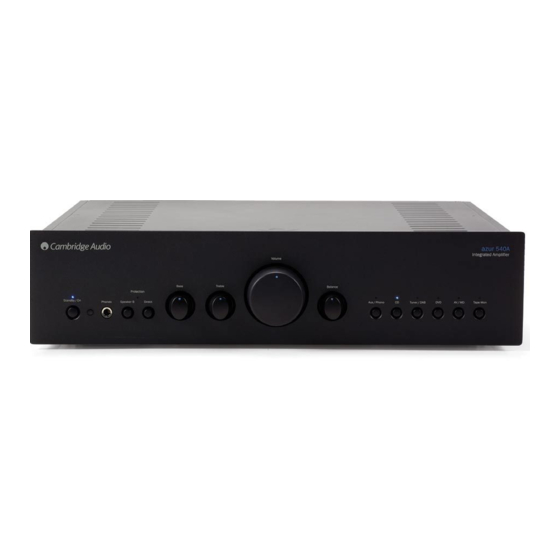
Cambridge Audio 540A User Manual
Hide thumbs
Also See for 540A:
- User manual (148 pages) ,
- Specifications (1 page) ,
- Brochure & specs (21 pages)
Advertisement
Advertisement

Summary of Contents for Cambridge Audio 540A
- Page 1 Amplifiers User’s manual ™...
-
Page 2: Table Of Contents
CONTENTS Introduction ....................3 Safety precautions ..................4 Installation....................5 Rear panel connections ................5 Operating instructions................7 Connection Diagrams................. 8 Troubleshooting..................13 Limited warranty..................14... -
Page 3: Introduction
Congratulations o o n p p urchasing t t his C C ambridge A A udio a a mplifier. I I t h h as recommend tuners and digital equipment from the Cambridge Audio been d d esigned u u sing t t he r r esults f f rom a a n e e xtensive R R esearch & &... -
Page 4: Safety Precautions
Should you lose the fuse carrier the correct The wire which is coloured BROWN must be part must be reordered from your Cambridge Audio dealer. connected to the terminal which is marked... -
Page 5: Installation
DAB tuner. Alternatively a turntable can be connected, but first a Do not plug a source component directly into a power amplifier unless it phono stage must be installed. Please contact your Cambridge Audio has a variable output level. - Page 6 P SERIES (POWER AMPLIFIERS) Connect the audio signal from a Compact Disc player to these sockets. Input/Output Alternatively, any line level audio signal may be connected here. Connect either of these pairs of sockets to the PRE-OUT sockets on your A-Series (where featured) or C-Series amplifiers.
-
Page 7: Operating Instructions
Amplifiers OPERATING INSTRUCTIONS Note: S S ome f f eatures m m ay n n ot a a pply t t o a a ll m m odels. R R efer t t o t t he d d iagram o o n R R e e m m o o t t e e s s e e n n s s o o r r your a a ccompanying O O wners’... -
Page 8: Connection Diagrams
FIGURE 1 FIGURE 2 INTEGRATED AMPLIFIER BASIC CONNECTIONS INTEGRATED AMPLIFIER BASIC CONNECTIONS (A1 SERIES) (A5 SERIES) - Page 9 Amplifiers FIGURE 3 FIGURE 4 CONTROL & POWER AMPLIFIER BASIC CONNECTIONS BI-WIRING WITH AN INTEGRATED AMPLIFIER AND BI-WIRABLE LOUDSPEAKERS (A1 SERIES)
- Page 10 FIGURE 5 FIGURE 6 BI-WIRING WITH AN INTEGRATED AMPLIFIER AND BI-AMPING WITH AN INTEGRATED AMPLIFIER AND BI-WIRABLE LOUDSPEAKERS (A5 SERIES) BI-WIRABLE LOUDSPEAKERS (A1 SERIES)
- Page 11 Amplifiers FIGURE 7 FIGURE 8 BI-AMPING WITH AN INTEGRATED AMPLIFIER AND BI-WIRING WITH A CONTROL/POWER COMBINATION BI-WIRABLE LOUDSPEAKERS (A5 SERIES)
- Page 12 FIGURE 9 FIGURE 7 BI-AMPING WITH A CONTROL/POWER COMBINATION BI-AMPING WITH A CONTROL/POWER COMBINATION ALTERNATIVE CONNECTIONS...
-
Page 13: Troubleshooting
540A/640A Integrated amplifer TROUBLESHOOTING There i i s n n o p p ower Ensure the AC power cord is connected securely. Ensure the plug is fully inserted into the wall socket and is switched on Check fuse in the mains plug or adaptor... -
Page 14: Limited Warranty
Cambridge Audio product, THIS PRODUCT. EXCEPT TO THE EXTENT PROHIBITED BY LAW, THIS it can be returned by your dealer to Cambridge Audio or an authorised WARRANTY IS EXCLUSIVE AND IN LIEU OF ALL OTHER EXPRESS AND Cambridge Audio service agent. - Page 15 540A/640A Integrated amplifer...
- Page 16 Amplifiers www.cambridge-a a udio.com Part No. AP10513/4...


Need help?
Do you have a question about the 540A and is the answer not in the manual?
Questions and answers
Cd tray comes out when instructed to play
The CD tray of the Cambridge Audio Azur 540C (not 540A) comes out after being closed because of a possible issue with the tray not seating properly, likely due to a loose belt or a sensor problem.
This answer is automatically generated