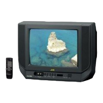
JVC AV-14F3 Service Manual

JVC AV-14F3 Service Manual

Hide thumbs Also See for AV-14F3:

Advertisement

SERVICE MANUAL
[ RM-C364GY]
[RM-C90]
CONTENTS
! SPECIFICATIONS ・・・・・・・・・・・・・・・・・ ・・・・・・・・・・ ・・・ ・・
・・・・・・・ ・・・・・・・・・・ ・・・・・・・・・・ ・・ ・・・
・・・・・・・ ・・・・・・・・・・ ・・・・・・・・・・ ・・・ ・・
・・・・・・・ ・・・・・・・・・・ ・・・・・・・・・・ ・・ ・・・ ・・ ・・・ ・・ ・・・・ ・・・・ ・・ ・・・・ ・・・・ ・・ ・・
! SAFETY PRECAUTIONS ・・・・・・・ ・・・・・・・・ ・・・・・・ ・・ ・・・・ ・・・ ・・
! FEATURES・・ ・・・ ・・ ・・・・・・・・・・ ・・・・・・・・・・・・ ・・・
・・・・・・・・・ ・・・・・・・・・・ ・・・・・・・・・・・・・
・・・・・・・・・ ・・・・・・・・・・ ・・・・・・・・・・・・・ ・・ ・・・ ・・・・・・ ・・・・ ・・・・・・ ・・・・ ・・・・・ ・・
・・ ・・・ ・・ ・・・・・・・・・・ ・・・・・・・・・・・・ ・・・
! FUNCTIONS ・・・ ・・ ・・・・・・・・・・ ・・・・・・・・・・ ・・・・・・・
・・・・・ ・・・・・・・・・・ ・・・・・・・・ ・・・・・・・・・・・ ・・・ ・・ ・・・・ ・・・・ ・・ ・・・・ ・・・・ ・・ ・・・ ・・
・・・ ・・ ・・・・・・・・・・ ・・・・・・・・・・ ・・・・・・・
・・・・・ ・・・・・・・・・・ ・・・・・・・・ ・・・・・・・・・
! MAIN DIFFERENCE LIST ・・・・・・・ ・・・・・・・・・・ ・・・・ ・・・・ ・・・・ ・・・
! SPECIFIC SERVICE INSTRUCTIONS ・・・・・・・ ・・・・ ・・・・ ・・・・ ・・ ・・・・ ・・・・ ・・・
! SERVICE ADJUSTMENTS ・・・・・・・ ・・・・・・・・・・ ・・・・ ・・・・ ・・・・ ・・・
! PARTS LIST ・・・・・・・・・ ・・・・・・・・・・ ・・・・・・・・・・ ・・・
・・・ ・・・・・・・・・・・・・・・・・・・・・・・・・・・・・・・ ・・・ ・・・・ ・・ ・・・・ ・・・・ ・・ ・・・・ ・・・・ ・・・
・・・・・・・・・ ・・・・・・・・・・ ・・・・・・・・・・ ・・・
・・・ ・・・・・・・・・・・・・・・・・・・・・・・・・・・・・
★ OPERATING INSTRUCTIONS
★ STANDARD CIRCUIT DIAGRAM ・・ ・・・ ・・・・・・・・・・ ・・ ・・ ・・・・ ・・・・ ・・ ・ ・・
1

COLOUR TELEVISION

AV-14FMG3
・・・・・・・・・ ・・・・・・・・ ・・・・ ・・・・ ・・・・ ・・・・・ ・・・ ・・・・ ・・ ・・・・ ・・・・ ・・ ・・
・・・・・・・ ・・・・・・・・ ・・・・・・ ・・ ・・・・ ・・・ ・・
・・・・・・・・・ ・・・・・・・・ ・・・・ ・・・・ ・・・・ ・・・
・・・・・・・・・・・・・・・・・・・・・ ・・ ・・・・ ・・・ ・・・・・ ・・・・ ・・ ・・・・ ・・・・ ・・ ・・・・
・・・・・・・ ・・・・・・・・・・ ・・・・ ・・・・ ・・・・ ・・・
・・・・・・・・・・・・・・・・・・・・・ ・・ ・・・・ ・・・ ・・
・・・・・・・・・・・ ・・・・ ・・ ・・・・ ・・・・ ・・ ・・・ ・・・・・ ・・・・ ・・・・ ・・
・・・・・・・・・・・ ・・ ・・ ・・・・ ・・・・ ・・ ・・・・ ・・・
・・・・・・・・・・・ ・・・・ ・・ ・・・・ ・・・・ ・・ ・・・ ・・
・・・・・・・・・・・・・・・・・・・・・ ・・ ・・・・ ・・・ ・・ ・・ ・ ・・ ・・・・ ・・・・ ・・ ・・・・ ・・
・・・・・・・・・・・・・・・・・・・・・ ・・ ・・・・ ・・・ ・・
・・・・・・・ ・・・・・・・・・・ ・・・・ ・・・・ ・・・・ ・・・
・・・・・ ・・・・・・・・・・ ・・・・ ・・ ・・・・ ・・・・ ・・・・・ ・・・ ・・ ・・・・ ・・・・ ・
・・・・・ ・・・・・・・・・・ ・・ ・・ ・・・・ ・・・・ ・・ ・ ・・
・・・・・ ・・・・・・・・・・ ・・・・ ・・ ・・・・ ・・・・ ・・・
CO PYRIGHT © 2002 VICTOR COMPANY OF JAPAN, LTD.
/-A
・・ ・・・ ・・ ・・・・ ・・・・ ・・ ・・・・ ・・・・ ・・ ・・
・・・ ・・・・・・ ・・・・ ・・・・・・ ・・・・ ・・・・・・ 2
・・・ ・・・・・・ ・・・・ ・・・・・・ ・・・・ ・・・・・・
・・・ ・・・・ ・・・・・・ ・・・・ ・・・・・・ 3
・・・ ・・・・ ・・・・・・ ・・・・ ・・・・・・
・・ ・・・ ・・・・ ・・ ・・・・ ・・・・ ・・ ・・
・・・ ・・ ・・・・ ・・・・ ・・ ・・・・ ・・・・ ・・ ・・・・ ・・・
・・・ ・・・・ ・・ ・・・・ ・・・・ ・・ ・・・・ ・・・・ ・・ ・ ・・ ・・ ・
・・ ・・・ ・・・・・・ ・・・・ ・・・・・・ ・・・・ ・・・・・ ・・
・・・ ・・ ・・・・ ・・・・ ・・ ・・・・ ・・・・ ・・ ・・・・ ・・・ ・・ ・・ ・・ ・・ 5
・・・ ・・ ・・・・ ・・・・ ・・ ・・・・ ・・・・ ・・ ・・・・ ・・・
・・ ・・・ ・・・・・・ ・・・・ ・・・・・・ ・・・・ ・・・・・ ・・
・・ ・・・ ・・・・ ・・ ・・・・ ・・・・ ・・ ・・ 7
・・・ ・・・・ ・・ ・・・・ ・・・・ ・・ ・・・・
・・ ・・・ ・・ ・・・・ ・・・・ ・・ ・・・・ ・・
・・ ・・・ ・・ ・・・・ ・・・・ ・・ ・・・・ 15
・・ ・・・ ・・ ・・・・ ・・・・ ・・ ・・・・
・・ ・ ・・ ・・・・ ・・・・ ・・ ・・・・ ・・
・・・ ・・・・ ・・ ・・・・ ・・・・ ・・ ・・・・ ・・・・ ・・ ・ ・・ ・ ・ ・ ・ 33
・・・ ・・・・ ・・・・ ・・ ・・・・ ・・・・ ・・ ・・・・ ・・・ ・・
・・ ・・・ ・・・・ ・・ ・・・・ ・・・・ ・・ ・・・・ ・・・・ ・・・
・・・ ・・・・ ・・ ・・・・ ・・・ 2-1
・・・ ・・・・ ・・ ・・・・ ・・・
・・ ・・・ ・・・・ ・・ ・・・・ ・
BASIC CHASSIS
CG
・・・ 4
・・ ・
・・・
・・ ・ ・・ ・・・・ ・・・・ 8
・・ ・・・ ・・・・ ・・ ・・
・・・ ・・・・ ・・・・ ・・
No. 52026
Jun. 2002

Advertisement

Table of Contents
loading

Summary of Contents for JVC AV-14F3

  • Page 1: Table Of Contents

    AV- 14F3/AV-1435 AV- 1435EE/AV-1435TEE AV- 14FMT3/AV-1438 AV- 14FMG3/AV- 14FMG3B SERVICE MANUAL COLOUR TELEVISION AV-14F3 / AV-1435 BASIC CHASSIS AV-1435EE / AV-1435TEE AV-14FMT3 / AV-1438 AV-14FMG3 / AV-14FMG3B AV-14FMG3 [ RM-C364GY] [RM-C90] [RM-C364] CONTENTS ! SPECIFICATIONS ・・・・・・・・・・・・・・・・・ ・・・・・・・・・・ ・・・ ・・ ・・・・・・・ ・・・・・・・・・・ ・・・・・・・・・・ ・・ ・・・...
  • Page 2: : Rm-C364

    RCA × 2 (Front / Rear) Output 1V(p-p), 75 Ω Video Audio 500mV( rms) (-4dBs), Low impedance, Hea dphone jack 3.5mm mini jack [AV-14F3 / AV-1435 / AV-1435EE] [AV-14FMG3 / AV-14FMG3 / AV-1438] : RM-C364G Y : RM-C364G Y [AV-1435TEE] [AV-14FMG3B] Rem ote Control Unit...
  • Page 3: Safety Precautions

    AV-14F3/AV-1435 AV-1435EE/AV-1435TEE AV-14FMT3/AV-1438 AV-14FMG3/AV- 14FMG 3B SAFETY PRECAUTIONS 1. The design of this product contains special hardware, many 9. Isolation Check circuits and components specially for safety purposes. For (Safety for Electrical Shock Hazard) continued protection, no changes should be made to the original After re-ass embling the product, always perform an isolation design unless authorized in writing by the manufacturer.
  • Page 4: Features

    AV-14F3/AV-1435 AV-1435EE/AV-1435TEE AV-14FMT3/AV-1438 AV-14FMG3/AV- 14FMG 3B FEATURES " New chassis design enables us e of an interactive on-screen c ontrol. " Wide range voltage (110V~240V) AC power input. " With AUDIO / VIDEO INPUT & OUTPUT terminal. " MUTING button can reduce the audio level to zero instantly.
  • Page 5: Functions

    AV-14F3/AV-1435 AV-1435EE/AV-1435TEE AV-14FMT3/AV-1438 AV-14FMG3/AV- 14FMG 3B FUNCTIONS ■ FRONT PANEL MENU buttons CHANNEL -/+ buttons VOLUME -/+ buttons AI ECO sensor REMOTE CONTROL s ens or ON TIMER lamp POWER lamp MAIN POWER button A/V INPUT terminal HEADPHONE jack [AV-1438] ■...
  • Page 6: Remote Control Unit

    MENU Number (CH.) key - / -- key VOLUME -/+ key Teletext k ey RM-C364GY : AV-14F3 / AV-1435 / AV-1435EE / AV-1438 / AV-14FMG3 / AV-14FMG3 RM-C364 : AV-14FMG3B ECO SENSOR key SOUND SYSTEM key COLOUR SYSTEM key TV/VIDEO key...
  • Page 7: Main Difference List

    AV-14F3/AV-1435 AV-1435EE/AV-1435TEE AV-14FMT3/AV-1438 AV-14FMG3/AV- 14FMG 3B MAIN DIFFERENCE LIST Part Name Mai n PWB Remote Control Unit Fr ont Cabinet Power Cord Model Name AV-14F3 SCG -1401A-H2 RM-C3 64GY-1H LC1 0831-022A-H QMPR340-165-K2 SCG -1420A-H2 AV-1435 LC1 0831-032A-H AV-1435EE SCG -1418A-H2...
  • Page 8: Specific Service Instructions

    AV-14F3/AV-1435 AV-1435EE/AV-1435TEE AV-14FMT3/AV-1438 AV-14FMG3/AV- 14FMG 3B SPECIFIC SERVICE INSTRUCTIONS REMOVING THE REAR COVER 1. Unplug the power plug. 2. As shown in figure, remove the screws marked and a " " " " screw marked 3. Withdraw the rear cover toward you.
  • Page 9 AV-14F3/AV-1435 AV-1435EE/AV-1435TEE AV-14FMT3/AV-1438 AV-14FMG3/AV- 14FMG 3B FRONT CABI. SPEAKER ( × × × × 2) CRT SOCKET MAIN PWB PWB STOPPER POWER CORD REAR COVER (× × × × 1) (× × × × 1) (× × × × 4)
  • Page 10 AV-14F3/AV-1435 AV-1435EE/AV-1435TEE AV-14FMT3/AV-1438 AV-14FMG3/AV- 14FMG 3B REPLACEMENT OF MEMORY ICs 1. MEMORY ICs This model uses memory ICs. This memory IC data are for proper operation of the video and deflection circuits. When replacing memory ICs, be sure to us e ICs written with the initial values of data.
  • Page 11: Av-14F3/Av-1435

    AV-14F3/AV-1435 AV-1435EE/AV-1435TEE AV-14FMT3/AV-1438 AV-14FMG3/AV- 14FMG 3B SETTING OF SYSTEM CONSTANT SET Setting value Setting item Setting contents 14 FMG3/- 14 35EE 14 35TEE 14 FMT3 14 FMG3 14 FMG3B 14 F3 14 35 14 38 MULTI. TRIPLE T RIPLE MU LTI...
  • Page 12: Av-14F3/Av-1435

    AV-14F3/AV-1435 AV-1435EE/AV-1435TEE AV-14FMT3/AV-1438 AV-14FMG3/AV- 14FMG 3B INITIAL SETTING VALUE OF SERVICE MENU Ad justment of the SERVICE MENU is m ade on the basis of the initial setting values ; however, the new setting values which set the screen in its optim um condition may differ from the initial setting.
  • Page 13 AV-14F3/AV-1435 AV-1435EE/AV-1435TEE AV-14FMT3/AV-1438 AV-14FMG3/AV- 14FMG 3B 5. PRESET The items in the following table, it is no requirem ent for adjustment. If values had changed by the miss operation, set the initial setting values in the following table. Colour System...
  • Page 14 AV-14F3/AV-1435 AV-1435EE/AV-1435TEE AV-14FMT3/AV-1438 AV-14FMG3/AV- 14FMG 3B REPLACEMENT OF IC301 (IF V/C DECODER) " For the IC301(IF V/C DECODER) of this model, all data are written in the micr o-computer. So, write the data in the micro- computer in accordance with the following procedures before starting adjustment.
  • Page 15: Adjustment Items

    AV-14F3/AV-1435 AV-1435EE/AV-1435TEE AV-14FMT3/AV-1438 AV-14FMG3/AV- 14FMG 3B SERVICE ADJUSTMENTS BEFORE STARTING SERVICE ADJUSTMENT 1. There ar e 2 way of adjusting this TV: One is with the 6. Never touch any adjustment parts, which ar e not specified REMOTE CONTROL UNIT and the other is the conventional in the list for this adjustment VRs, transfor ms, condenser s, method using adjustment parts and components.
  • Page 16 AV-14F3/AV-1435 AV-1435EE/AV-1435TEE AV-14FMT3/AV-1438 AV-14FMG3/AV- 14FMG 3B BASIC OPERATION OF SERVICE MENU " The adjustment using SERVICE MENU The following adjus tment items use the SERVICE MENU in the series of the adjustment. The adjustments are made on the bas is of the initial setting values.
  • Page 17 %・ If it is ON, then you turn the TV power off, when you are turn the TV power on again. The JVC’s logo will be shown about 15 s econds automatically. ② MENU -/+ Key ・・・・・・・ ・・・・・・・・・・ Select Language.
  • Page 18 AV-14F3/AV-1435 AV-1435EE/AV-1435TEE AV-14FMT3/AV-1438 AV-14FMG3/AV- 14FMG 3B SERVICE MENU FLOW CHART SERVICE MENU SUB MENU 1. IF VCO (CW) ***.** M Hz TOO HIGH SERVICE MENU ABOVE REFERENCE 1.IF 2.V/C JUST REFERENCE 3.DEF 4.VSM PRESET BELOW REFERENCE 1. VCO 5.PRESET TOO LOW 6.SETUP TOUR OFF...
  • Page 19: Main Pwb

    AV-14F3/AV-1435 AV-1435EE/AV-1435TEE AV-14FMT3/AV-1438 AV-14FMG3/AV- 14FMG 3B ADJUSTMENT LOCATIONS CRT SOCKET PWB (SOLDER SIDE) TP-47R/G TP-47G/R TP-47B TP-E CRT EARTH WIRE (BRAIDED ASS'Y) MAIN PWB FRONT F901 IC702 IC701 MEMORY IC IC821 [On ly fo r AV-1 435 TEE / AV -1 4FMT3 ]...
  • Page 20: Focus Adjustment

    AV-14F3/AV-1435 AV-1435EE/AV-1435TEE AV-14FMT3/AV-1438 AV-14FMG3/AV- 14FMG 3B ADJUSTMENTS B1 POWER SUPPLY Measuring Item Test point Ad justment part Description instrument Check of Signal TP-91 ( B1) 1. Input a whole black signal. B1 Power gener ator TP-E ( # # # # ) 2.
  • Page 21 AV-14F3/AV-1435 AV-1435EE/AV-1435TEE AV-14FMT3/AV-1438 AV-14FMG3/AV- 14FMG 3B Measuring Item Test point Ad justment part Description instrument Signal Ad justment DELAY POINT 1. Input a blac k and white signal (colour off). gener ator of DELAY (AGC TAKE-OVER) 2. Enter the SERVICE MENU.
  • Page 22 AV-14F3/AV-1435 AV-1435EE/AV-1435TEE AV-14FMT3/AV-1438 AV-14FMG3/AV- 14FMG 3B VIDEO / CHROMA CIRCUIT ADJUSTMENT The setting (adjustment) using the REMOTE CONTROL UNIT is made on the basis of the initial setting values. The setting values which adjust the scr een to the optimum condition can be different from the initial setting values.
  • Page 23 AV-14F3/AV-1435 AV-1435EE/AV-1435TEE AV-14FMT3/AV-1438 AV-14FMG3/AV- 14FMG 3B Measuring Item Test point Ad justment part Description instrument Remote Ad justment 3. BRIGHT 1. Receive any broadc ast. control unit 2. Enter the SERVICE MENU. SUB BRIGHT 3. Select 2. V/C from SERVICE MENU.
  • Page 24 AV-14F3/AV-1435 AV-1435EE/AV-1435TEE AV-14FMT3/AV-1438 AV-14FMG3/AV- 14FMG 3B Measuring Item Test point Ad justment part Description instrument Ad justment Signal TP-47G/R 5. COLOUR [Method of adjustm ent using measur ing instrument] gener ator of SUB COLOUR Ⅱ Ⅱ Ⅱ Ⅱ TP-E (# # # # )
  • Page 25 AV-14F3/AV-1435 AV-1435EE/AV-1435TEE AV-14FMT3/AV-1438 AV-14FMG3/AV- 14FMG 3B Measuring Item Test point Ad justment part Description instrument Signal Ad justment 6. TINT [Method of adjustm ent without m easuring instrument] gener ator of TINTⅠ Ⅰ Ⅰ Ⅰ Remote NT SC 3.58 T INT 1.
  • Page 26 AV-14F3/AV-1435 AV-1435EE/AV-1435TEE AV-14FMT3/AV-1438 AV-14FMG3/AV- 14FMG 3B Measuring Item Test point Ad justment part Description instrument Remote Ad justment 7.SECAM [Method of adjustment using measur ing instrument] control unit of SECAM BL ADJUST BL ACK 1. Input a SECAM full field c olour bar signal.
  • Page 27 AV-14F3/AV-1435 AV-1435EE/AV-1435TEE AV-14FMT3/AV-1438 AV-14FMG3/AV- 14FMG 3B DEFLECTION CIRCUIT ADJUSTMENT " There are 2 modes of adjustment (s etting value) ------ ① 50Hz mode and ② 60Hz mode ----- depending upon the kind of s ignals (vertic al frequency 50Hz / 60Hz).
  • Page 28 AV-14F3/AV-1435 AV-1435EE/AV-1435TEE AV-14FMT3/AV-1438 AV-14FMG3/AV- 14FMG 3B Measuring Item Test point Ad justment part Description instrument Signal ● ● ● ● When the vertical linearity been deteriorated Ad justment 4. VER. L IN. gener ator of VER. LIN. 5. VER. SCURVE rem arkably, perform the following steps.
  • Page 29: Purity Adjustment

    AV-14F3/AV-1435 AV-1435EE/AV-1435TEE AV-14FMT3/AV-1438 AV-14FMG3/AV- 14FMG 3B PURITY / CONVERGENCE ADJUSTMENT PURITY ADJUSTMENT 1. Demagnetize CRT with the demagnetizer. W EDGE DEF LECT ION 2. Loosen the retainer screw of the deflec tion yoke. YOKE 3. Remove the wedges. CR T 4.
  • Page 30 AV-14F3/AV-1435 AV-1435EE/AV-1435TEE AV-14FMT3/AV-1438 AV-14FMG3/AV- 14FMG 3B STATIC CONVERGENCE ADJUSTMENT 1. Input a cross hatch signal. 2. Using 4-pole convergence magnets , overlap the red and blue lines in the center of the screen (Fig.1) and turn them to magenta (red/blue).
  • Page 31: Replacement Of Chip Component

    AV-14F3/AV-1435 AV-1435EE/AV-1435TEE AV-14FMT3/AV-1438 AV-14FMG3/AV- 14FMG 3B REPLACEMENT OF CHIP COMPONENT ! CAUTIONS 1. Avoid heating for more than 3 seconds. 2. Do not rub the electrodes and the resist parts of the pattern. 3. When removing a c hip part, melt the s older adequately.
  • Page 32 AV-14F3/AV-1435 AV-1435EE/AV-1435TEE AV-14FMT3/AV-1438 AV-14FMG3/AV- 14FMG 3B No.52026...

Table of Contents