N-Tron 102MC User Manual & Installation Manual

N-Tron 102MC User Manual & Installation Manual

100 series media converter & industrial ethernet switches

Advertisement

100 Series
Media Converter &
Industrial Ethernet Switches
User Manual &
Installation
Guide
(Revised 2011-04-15)
1

Advertisement

Table of Contents
loading

Summary of Contents for N-Tron 102MC

  • Page 1: User Manual

    100 Series Media Converter & Industrial Ethernet Switches User Manual & Installation Guide (Revised 2011-04-15)
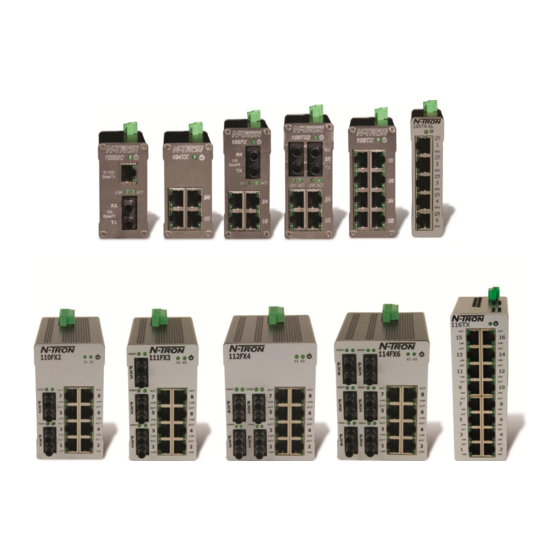
  • Page 2 Industrial Media Converter and Ethernet Switch Installation Guide 102MC-XX 105TX 106FX2 110FX2-XX-YY 102MCE-XX-YY 105TX-SL 108TX 111FX3-XX-YY 104TX 105FX-XX 108TX-HV 112FX4-XX-YY 105FXE-XX-YY 114FX6-XX-YY 116TX Where: XX=ST or SC and YY= 15, 40 or 80 (Revised 2011-04-15)
  • Page 3 In no event shall N-TRON Corp. be liable for any incidental, special, indirect or consequential damages whatsoever included but not limited to lost profits arising out of errors or omissions in this manual or the information contained herein.
  • Page 4: General Safety Warnings

    Do not operate the equipment in the presence of flammable gasses or fumes. Operating electrical equipment in such an environment constitutes a definite safety hazard. WARNING: If the equipment is used in the manner not specified by N-TRON Corp., the protection provided by the equipment may be impaired.
  • Page 5: Hazardous Location Installation Requirements

    4. WARNING: Explosion Hazard - Do not remove or replace the device unless power has been switched off or the area is known to be non-hazardous. 5. For 102MC, 105FX, 106FX and 108TX: Use 60/75ºC rated copper wire, (0.22Nm) 2 inch-lbs. tightening torque for field installed connectors. For 104TX, 105TX and 105TX-SL: Use 95°C rated copper wire, (0.22Nm) 2 inch-lbs.
  • Page 6 All fiber products utilize the IEEE compliant SC or ST duplex connectors for fiber optic communications. All 10/100Base-TX ports utilize the RJ45 shielded connectors. The 102MC/MCE is a two-port unmanaged media converter that converts 10/100BaseTX copper to 100BaseFX full duplex fiber.
  • Page 7: Package Contents

    PACKAGE CONTENTS Please make sure the package contains the following items: 100 Series Media Converter or Ethernet Switch Instruction Sheet Contact your carrier if any items are damaged. UNPACKING Remove all the equipment from the packaging, and store the packaging in a safe place. File any damage claims with the carrier.
  • Page 8 DIN-Rail Mounting Install the unit in a standard DIN rail. Recess the unit to allow at least 2” of horizontal clearance for CAT5e cable bend radius. To install the plastic clip units to 35mm To remove the plastic clip units from the industrial DIN rail, place the top edge of the 35mm industrial DIN rail, place a flat head included mounting bracket on the back of the...
  • Page 9 URMK 1000-PM Most N-Tron™ products are designed to be mounted on industry standard 35mm DIN rail. However, DIN rail mounting may not be suitable for all applications. Our Universal Rack Mount Kit (P/N: URMK) may be used to mount the 100 Series enclosures to standard 19" racks, and our Panel Mount Assembly (P/N: 1000-PM) may be used to mount the metal clip versions of the 100 Series enclosures to a panel or any other flat surface.
  • Page 10: Front Panel

    FRONT PANEL From Top to Bottom: Speed LED LNK/ACT Link/Activity LED RJ45 Ports Auto sensing 10/100BaseT Connection Green LED lights when Power is connected NOTE: The top LED indicates Link/Activity (LNK/ACT), and the lower LED indicates Speed (SPD) status. (Revised 2011-03-14)
  • Page 11: Applying Power

    Link established, no Activity on cable. BLINKING Link established, Activity on cable LNK/ACT No link activity on cable. LINK is 100Mbps. Link is 10Mbs. APPLYING POWER • 102MC, 104TX, 105TX, 105FX, 106FX2, 108TX, and 116TX Power Connector (Top View) (Revised 2011-03-14)
  • Page 12 The power cord should be limited to less than 10 meters in order to ensure optimum performance. Recommended 24V DC Power Supplies, similar to: 100-240VAC: N-Tron NTPS-24-1.3, DC 24V/1.3 • 105TX-SL (Top View) Unscrew & Remove the DC Voltage Input Plug from the top header. Install the DC Power Cables into the Plug (observing polarity on unit).
  • Page 13 102MC, 104TX, 105TX, 105FX, 106FX2 and 108TX part of the design. N-Tron switches are designed to be grounded, but the user has been given the flexibility to float the switch when required. The best noise immunity and emissions (i.e. CE) are obtained when the N-Tron switch chassis is connected to earth ground via a drain wire.
  • Page 14: Rj45 Connector Crimp Specifications

    105TX-SL METALLIC DIN-RAIL CLIP DRAIN WIRE WITH LUG CONNECTING SWITCH CHASSIS TO KNOWN GOOD GROUNDING POINT. DRAIN WIRE WITH LUG CONNECTING SWITCH CHASSIS TO KNOWN GOOD GROUNDING POINT. In the event all Cat5e patch cable distances are small (i.e. All Ethernet devices are located the same local cabinet and/or referenced to the same earth ground), it is permissible to use fully shielded cables terminated to chassis ground at both ends in systems void of low level analog signals.
  • Page 15: Connecting The Unit

    ~ 2X. 3. Verify that Link LED’s are ON for connected ports. 4. Verify cabling used between stations. 5. Verify that cabling is Category 3 or greater for 10Mbit Operation. SUPPORT Contact N-Tron Corporation at: TEL: 251-342-2164 FAX: 251-342-6353 www.n-tron.com N-TRON_Support@n-tron.com...
  • Page 16: Fcc Statement

    FCC STATEMENT This product complies with Part 15 of the FCC-A Rules. Operation is subject to the following conditions: (1) This device may not cause harmful Interference (2) This device must accept any interference received, including interference that may cause undesired operation.
  • Page 17 100BaseFX: SC or ST Duplex Port Recommended Minimum Wiring Clearance: Top: 1 " (2.54 cm) Front: 4 " (10.16 cm) Warranty: Effective January 1, 2008, all N-TRON products carry a 3 year warranty from the date of purchase. (Revised 2011-03-14)
  • Page 18 Regulatory Approvals: Safety: Suitable for use in Class I, Division 2, Groups A, B, C and D Hazardous Locations, or Nonhazardous Locations only. EMI: EN61000-6-4, EN55011 - Class A FCC Title 47, Part 15, Subpart B - Class A ICES-003 – Class A EMS: EN61000-6-2 EN61000-4-2 (ESD) EN61000-4-3 (RS)
  • Page 19 > Cat-5 Cable Connectors 10/100BaseT: RJ45 UTP Ports Recommended Minimum Wiring Clearance: Top: 1 " (2.54 cm) Front: 2 " (5.08 cm) Warranty: Effective January 1, 2008, all N-TRON products carry a 3 year warranty from the date of purchase. (Revised 2011-03-14)
  • Page 20 Regulatory Approvals: Safety: Suitable for use in Class I, Division 2, Groups A, B, C and D Hazardous Locations, or Nonhazardous Locations only. EMI: EN61000-6-4, EN55011 - Class A FCC Title 47, Part 15, Subpart B - Class A ICES-003 – Class A EMS: EN61000-6-2 EN61000-4-2 (ESD) EN61000-4-3 (RS)
  • Page 21 Cat5 Cable Connectors 10/100BaseT: Five (5) RJ45 UTP Ports Recommended Minimum Wiring Clearance: Top: 1" (2.54 cm) Front: 2" (5.08 cm) Warranty: Effective January 1, 2008, all N-TRON products carry a 3 year warranty from the date of purchase. (Revised 2011-03-14)
  • Page 22 Regulatory Approvals: Safety: Suitable for use in Class I, Division 2, Groups A, B, C and D Hazardous Locations, or Nonhazardous Locations only. EMI: ANSI C63.4 FCC Title 47, Part 15, Subpart B - Class A ICES-003 – Class A EMC: EN61000-6-4 –...
  • Page 23 Two (2) ST or SC Duplex Ports Recommended Minimum Wiring Clearance: Top: 1 " (2.54 cm) Front: 4 " (10.16 cm) Warranty: Effective January 1, 2008, all N-TRON products carry a 3 year warranty from the date of purchase. (Revised 2011-03-14)
  • Page 24 Regulatory Approvals: Safety: Suitable for use in Class I, Division 2, Groups A, B, C and D Hazardous Locations, or Nonhazardous Locations only. EMI: IEC61000-6-2, EN55011 - Class A FCC Title 47, Part 15, Subpart B - Class A ICES-003 – Class A EMS: EN61000-6-2 EN61000-4-2 (ESD) EN61000-4-3 (RS)
  • Page 25 10/100BaseT: Eight (8) RJ45 UTP Ports Recommended Minimum Wiring Clearance: Top: 1 " (2.54 cm) Front: 2 " (5.08 cm) Warranty: Effective January 1, 2008, all N-TRON products carry a 3 year warranty from the date of purchase. (Revised 2011-03-14)
  • Page 26 Regulatory Approvals: Safety: Suitable for use in Class I, Division 2, Groups A, B, C and D Hazardous Locations, or Nonhazardous Locations only. The high voltage model is TÜV approved GS per EN 60950-1. EMI: EN61000-6-4, EN55011 - Class A FCC Title 47, Part 15, Subpart B - Class A ICES-003 –...
  • Page 27 100BaseFX: SC or ST Duplex Port Recommended Minimum Wiring Clearance: Top: 1 " (2.54 cm) Front: 4 " (10.16 cm) Warranty: Effective January 1, 2008, all N-TRON products carry a 3 year warranty from the date of purchase. (Revised 2011-03-14)
  • Page 28 Regulatory Approvals: Safety: Suitable for use in Class I, Division 2, Groups A, B, C and D Hazardous Locations, or Nonhazardous Locations only. EMI: EN 61000-6-4, EN 55011 - Class A FCC Title 47, Part 15, Subpart B - Class A ICES-003 –...
  • Page 29 Two (2) ST or SC Duplex Ports Recommended Minimum Wiring Clearance: Top: 1 " (2.54 cm) Front: 4 " (10.16 cm) Warranty: Effective January 1, 2008, all N-TRON products carry a 3 year warranty from the date of purchase. (Revised 2011-03-14)
  • Page 30 Regulatory Approvals: Safety: Suitable for use in Class I, Division 2, Groups A, B, C and D Hazardous Locations, or Nonhazardous Locations only. EMI: FCC CFR Title 47, Part 15, Subpart B - Class A ICES-003 – Class A EMC: EN61000-6-2/4 EN61000-4-2 (ESD) EN61000-4-3 (RS) EN61000-4-4 (EFT)
  • Page 31 Two (2) ST or SC Duplex Ports Recommended Minimum Wiring Clearance: Top: 1 " (2.54 cm) Front: 4 " (10.16 cm) Warranty: Effective January 1, 2008, all N-TRON products carry a 3 year warranty from the date of purchase. (Revised 2011-03-14)
  • Page 32 Regulatory Approvals: Safety: Suitable for use in Class I, Division 2, Groups A, B, C and D Hazardous Locations, or Nonhazardous Locations only. EMI: FCC CFR Title 47, Part 15, Subpart B - Class A ICES-003 – Class A EMC: EN61000-6-2/4 EN61000-4-2 (ESD) EN61000-4-3 (RS) EN61000-4-4 (EFT)
  • Page 33 Four (4) ST or SC Duplex Ports Recommended Minimum Wiring Clearance: Top: 1 " (2.54 cm) Front: 4 " (10.16 cm) Warranty: Effective January 1, 2008, all N-TRON products carry a 3 year warranty from the date of purchase. (Revised 2011-03-14)
  • Page 34 Regulatory Approvals: Safety: Suitable for use in Class I, Division 2, Groups A, B, C and D Hazardous Locations, or Nonhazardous Locations only. EMI: FCC CFR Title 47, Part 15, Subpart B - Class A ICES-003 – Class A EMC: EN61000-6-2/4 EN61000-4-2 (ESD) EN61000-4-3 (RS) EN61000-4-4 (EFT)
  • Page 35 Four (4) ST or SC Duplex Ports Recommended Minimum Wiring Clearance: Top: 1 " (2.54 cm) Front: 4 " (10.16 cm) Warranty: Effective January 1, 2008, all N-TRON products carry a 3 year warranty from the date of purchase. (Revised 2011-03-14)
  • Page 36 Regulatory Approvals: Safety: Suitable for use in Class I, Division 2, Groups A, B, C and D Hazardous Locations, or Nonhazardous Locations only. EMI: FCC CFR Title 47, Part 15, Subpart B - Class A ICES-003 – Class A EMC: EN61000-6-2/4 EN61000-4-2 (ESD) EN61000-4-3 (RS) EN61000-4-4 (EFT)
  • Page 37 Cat5 Cable Connectors 10/100BaseTX Sixteen (16) RJ-45 TX Ports Recommended Minimum Wiring Clearance: Top: 1" (2.6 cm) Front: 2" (5.1 cm) Warranty: Effective January 1, 2008, all N-TRON products carry a 3 year warranty from the date of purchase. (Revised 2011-03-14)
  • Page 38 Regulatory Approvals: Safety: Suitable for use in Class I, Division 2, Groups A, B, C and D Hazardous Locations, or Nonhazardous Locations only. EMI: ANSI C63.4 FCC CFR Title 47, Part 15, Subpart B - Class A ICES-003 – Class A EMC: EN61000-6-4 –...
  • Page 39 N-TRON, Corp. warrants to the end user that this hardware product will be free from defects in workmanship and materials, under normal use and service, for the applicable warranty period from the date of purchase from N-TRON or its authorized reseller. If a product does not operate as warranted during the applicable warranty period, N-TRON shall, at its option and expense, repair the defective product or part, deliver to customer an equivalent product or part to replace the defective item, or refund to customer the purchase price paid for the defective product.

Table of Contents