Table of Contents
Advertisement
Advertisement
Table of Contents

Related Manuals for NetworX NX-8V2

Summary of Contents for NetworX NX-8V2
- Page 1 ™ NetworX NX-8V2 LED Keypad User Manual...
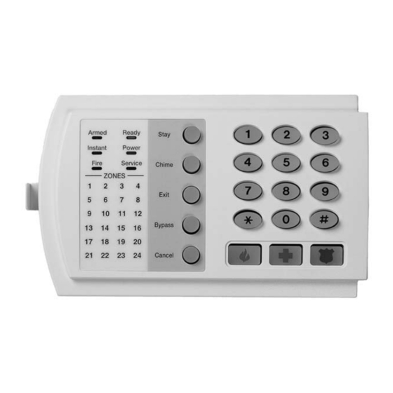
- Page 2 NX-8V2 SYSTEM POWER Light is “on” when READY Light is “on” when SERVICE Light is “on” to AC power is present; flashes the system is ready to arm; indicate a trouble condition to indicate a low battery KEYPAD flashes if ready to “force with your system.
- Page 3 SECURITY SYSTEM NOTES Installing/Service Company _________________________________ For Service Call __________________________________________ Central Station ___________________________________________ Duress Code ____________________ FUNCTION CODES Function Code Controls Function This system is not partitioned. EMERGENCY ACTIVATION KEYS (check if enabled) Fire Auxiliary Emergency Police PROGRAMMED FUNCTIONS Abort Delay (s) Cancel Alarm Forced Arming (s) Auto Bypass (s)
- Page 4 THIS MANUAL IS FURNISHED TO HELP YOU UNDERSTAND YOUR SECURITY SYSTEM AND BECOME PROFICIENT IN ITS OPERATION. ALL USERS OF YOUR SECURITY SYSTEM SHOULD READ AND FOLLOW THE INSTRUCTIONS AND PRECAUTIONS IN THIS BOOKLET. FAILURE TO DO SO COULD RESULT IN THE SECURITY SYSTEM NOT WORKING PROPERLY.
-
Page 5: Table Of Contents
TABLE OF CONTENTS GLOSSARY OF TERMS ................4 UNDERSTANDING THE LIGHTS ............5 Armed Light ..................5 Bypass Light..................5 Cancel Light ..................5 Chime Light ..................5 Exit Light...................5 Fire Light ..................5 Instant Light..................5 Power Light ..................5 Ready Light ..................6 Stay Light ..................6 Zone Light ..................6 EMERGENCY ACTIVATION KEYS ............6 KEYPAD FUNCTIONS ................7 Arming Your System In The “Away”... -
Page 6: Glossary Of Terms
GLOSSARY OF TERMS Abort Delay: An option that allows a delay in reporting to the central station. There is a communicator delay of 30 seconds. It can be removed, or increased up to 45 seconds at the option of the end user by consulting with the installer. Authority Level: The level of access an individual has when using an alarm panel. -
Page 7: Understanding The Lights
UNDERSTANDING THE LIGHTS Armed Light The armed light is “on” when the system is armed. The armed light is “off” when it is disarmed. The armed light will flash when there has been an alarm during the previous arm cycle. Bypass Light The bypass light is “on”... -
Page 8: Ready Light
Ready Light The ready light is “on” when the system is ready to arm and “flashes” if ready to force arm. The ready light is off when the system is not ready to arm because of a zone(s) being faulted. Stay Light The stay light is “on”... -
Page 9: Keypad Functions
KEYPAD FUNCTIONS ARMING YOUR SYSTEM IN THE “AWAY” MODE AWAY is used when the user is away from the premise and wants the interior protected. Listed below are the steps to arm in the AWAY Mode: Step 1 Close all protected doors and windows. •... -
Page 10: Using The Quick Arm
• Press the [STAY] key. Step 3 • The stay light will illuminate indicating that all interior zones are bypassed. (All interior devices will bypass automatically, giving the user freedom of movement within the interior area.) • The bypass light will illuminate if any zone(s) are bypassed. If any zone(s) have been bypassed previously by the user, the light(s) corresponding to the bypassed zone(s) will illuminate, alerting the user that a zone(s) may be unprotected and can be faulted without... -
Page 11: Cancel / Abort Feature
CANCEL / ABORT FEATURE (Optional, see page 1) The cancel light will flash during an abort delay time. If a code is entered followed by the [CANCEL] key while this light is flashing, all abortable reports will stop the communication process. Entering a code followed by the [CANCEL] key during or after an alarm report to the central station will cause the cancel light to come on. -
Page 12: Changing User Codes
CHANGING USER CODES Step 1 Your system must be in the Disarmed state to change user codes. Step 2 Press [r]-[5]. Step 3 Enter a “Master Arm/Disarm Code”. NOTE: For partitioned systems, someone changing the code of another person must have access to all or more partitions than the user being changed. - Page 13 LIGHT AUTHORITY LEVELS IF LIGHT 8 IS OFF Reserved (Note: Do not change if on.) Arm Only Arm Only After Closing Time Master Arm/Disarm (can program other codes) Arm/Disarm Bypass Zones Open / Close Reporting If this light is on, this code is programmed as a function code.
-
Page 14: Other Keypad Functions
OTHER KEYPAD FUNCTIONS SETTING THE KEYPAD TONE Step 1 Press [r]-[0]. Keypad is now in the “Adjust Tone” mode. Step 2 Pressing the [1] key will make the keypad sounder go to higher tones, pressing the [2] key will make the keypad sounder go to lower tones. -
Page 15: Reset Function
zone(s) will be displayed on the LCD keypad. It will also be entered into alarm memory and the internal log. Step 3 The keypad will begin to beep after 15 minutes in this mode. This beeping indicates that the “Walk-Test” mode will be automatically exited in 5 minutes. -
Page 16: Keypad Control Tones (Beeps)
Time Hour Code Time Hour Code Time Hour Code 12:00 8:00 AM 4:00 PM Midnight 1:00 AM 9:00 AM 5:00 PM 2:00 AM 10:00 AM 6:00 PM 3:00 AM 11:00 AM 7:00 PM 12:00 4:00 AM 8:00 PM Noon 5:00 AM 1:00 PM 9:00 PM 6:00 AM... -
Page 17: Service Menu
SERVICE MENU The service light will be “on” if the security system requires service. If the service light is “on”, press the [r] key followed by the [2] key to determine the service condition. One or more zone lights will illuminate indicating what service(s) is required. -
Page 18: Emergency Evacuation Plans
EMERGENCY EVACUATION PLANS An emergency evacuation plan should be established for an actual fire alarm condition. For example, the following steps are recommended by the National Fire Protection Association and can be used as a guide in establishing an evacuation plan for your building. Draw up a floor plan of your home. - Page 19 SYSTEM NOTES...
- Page 20 NX-8V2 USER’S MANUAL NX8V2UA04 REV A (FEB 2004)
Need help?
Do you have a question about the NX-8V2 and is the answer not in the manual?
Questions and answers