Table of Contents
Advertisement
Advertisement
Table of Contents

Related Manuals for XFX nForce 750a


Summary of Contents for XFX nForce 750a
- Page 1 User Guide XFX nForce 750a SLI Motherboard...
-
Page 3: Table Of Contents
Table of Contents Chapter 1 Introduction ................... 3 1.1 Package Checklist ....................... 1.2 Specifications ........................1.3 Motherboard Layout ....................... 1.4 Connecting Rear Panel I/O Devices ................6 Chapter 2 Hardware Setup ..................7 2.1 Choosing a Computer Chassis ....................2.2 Installing Motherboard ......................2.3 Installation of the CPU and CPU Cooler................ -
Page 5: Specifications
XFX nForce 750a Motherboard User's Guide 1.2 Specifications - Supports AMD® Socket AM2+/ AM2 processors: - AMD Phenom™FX / Phenom™ / Athlon™ 64 FX / Athlon™ 64 X2 Dual- Core/ Athlon™ 64 / Sempron™ /Cool 'n' Quiet Technology - Supports Hyper Transport Bus 5200/2000 MT/s (HT 3.0/1.0) -
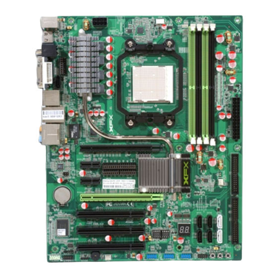
Page 6: Motherboard Layout
XFX nForce 750a Motherboard User's Guide 1.3 Motherboard Layout (This picture is only for reference) - 5 -... -
Page 7: Connecting Rear Panel I/O Devices
XFX nForce 750a Motherboard User's Guide 1.4 Rear I/O Panel (This picture is only for reference) • PS/2 Keyboard: Connects to PS/2 keyboard. • PS/2 Mouse: Connects to PS/2 mouse. • HDMI:Connects to multimedia devices with an HDMI port. • SPDIF IN:This connector provides an S/PDIF-IN connection. -
Page 8: Chapter 2 Hardware Setup
XFX nForce 750a Motherboard User's Guide Chapter 2 Hardware Setup 2.1 Choosing a Computer Chassis The motherboard and its component layouts illustrated in this chapter are only for reference. • Choose a chassis big enough to install this motherboard. • As some features for this motherboard are implemented by cabling connectors on the motherboard to indicators and switches or buttons on the chassis, make sure your chassis supports all the features required. -
Page 9: Installation Of The Cpu And Cpu Cooler
XFX nForce 750a Motherboard User's Guide 2.3 Installing CPU and CPU Cooler Before installing the CPU: 1. Please make sure that the motherboard supports the CPU. 2. Please take note of the indented corners of the CPU. If you install the CPU in the wrong direction, the CPU will not insert properly. -
Page 10: Installation Of Memory Modules
XFX nForce 750a Motherboard User's Guide 2.3.2 Installation of the CPU Cooler For proper installation, please kindly refer to the instruction manuals of your CPU Cooler. 2.4 Installation of Memory Modules This motherboard provides four 240-pin DDRII (Double Data Rate) DIMM slots, and supports Dual Channel Memory Technology. -
Page 11: Connecting Peripheral Devices
XFX nForce 750a Motherboard User's Guide 2.5 Connecting Peripheral Devices 2.5.1 Floppy and IDE Disk Drive Connectors Each of the IDE port connects up to two IDE drives at Ultra ATA 133/100/66/33 mode by one 40-pin, 80-conductor,and 3-connector Ultra ATA/66 ribbon cables. -
Page 12: Chapter 3 Jumpers & Headers Setup
XFX nForce 750a Motherboard User's Guide Chapter 3 Jumpers & Headers Setup 3.1 Checking Jumper Settings • For a 2-pin jumper, plug the jumper cap on both pins will make it CLOSE (SHORT). Remove the jumper cap, or plug it on either pin (reserved for future use) will leave it at OPEN position. -
Page 13: Fan Power Connectors
XFX nForce 750a Motherboard User's Guide 3.4 FAN Power Connectors These connectors each provide power to the cooling fans installed in your system. CFAN or CFAN1: CPU Fan Power Connector SYSFAN1/2: System Fan Power Connector SYSFAN1/2 These fan connectors are not jumpers. DO NOT place jumper caps on these connectors. -
Page 14: Additional Usb Port Headers
XFX nForce 750a Motherboard User's Guide 3.6 Additional USB Port Headers Pin Assignment Pin Assignment Data 0- Data 0- Data 0+ Data 0+ Ground Ground No Pin 3.7 Front Panel Audio Connection Header Audio: Pin No. Label Definition Mic In... -
Page 15: Serial Port Header(Jcom1)
XFX nForce 750a Motherboard User's Guide 3.8 Serial Port Header (Optional) This JCOM1 header supports a serial port module. Pin Assignment Pin Assignment 3.9 HDMI Jumper Setting This jumper is prepare for HDMI function. When pin 1 & 2 is shorted, DVI port is enabled and HDMI port is disabled. -
Page 16: Atx Power Input Connectors
XFX nForce 750a Motherboard User's Guide 3.10 ATX Power Input Connectors This motherboard provides two power connectors to connect power supplier. 3.11 RCA_SLC Jumper This jumper is prepare for S/PDIF IN or S/PDIF OUT. When pin 1& 2 shorted, S/PDIF IN is enabled. -
Page 17: Sli Jumper
XFX nForce 750a Motherboard User's Guide 3.12 SLI Jumper The Jumper of JSLI1,JSLI2,JSLI3,JSLI4 are prepare for SLI function, while they are all be shorted #pin 1-2, this is normal state; but while they are all be shorted #pin 2-3, there will be support SLI MODE. -
Page 18: Chapter 4 Bios Setup Utility
XFX nForce 750a Motherboard User's Guide Chapter 4 BIOS Setup Utility BIOS stands for Basic Input and Output System. It was once called ROM BIOS when it was stored in a Read-Only Memory (ROM) chip. Now manufacturers would like to store BIOS in EEPROM which means Electrically Erasable Programmable Memory. -
Page 19: Bios Setup - Cmos Setup Utility
XFX nForce 750a Motherboard User's Guide 4.5 BIOS Setup — CMOS Setup Utility • In order to increase system stability and performance, our engineering staff is constantly improving the BIOS menu. The BIOS setup screens and descriptions illustrated in this manual are for your reference only, and may not completely match with what you see on your screen. -
Page 20: Control Keys
XFX nForce 750a Motherboard User's Guide 4.5.2 Control Keys Press F1 to pop up a small help window that describes the appropriate keys to use and the possible selections for the highlighted item. Please check the following table for the function description of each control key. -
Page 21: Advanced Setting
XFX nForce 750a Motherboard User's Guide 4.5.3 Advanced Setting BIOS SETUP UTILITY Main Advanced Boot Security Power JUSTwOOT! Exit Advanced Settings Configure CPU. WARNING: Setting wrong values in below sections may cause system to malfunction. ► CPU Configuration ► Chipset ►... -
Page 22: Palette Snooping
XFX nForce 750a Motherboard User's Guide ► Chipset Click <Press Enter> key to enter its submenu, that can select primary graphics adapter from optional items, or set Internal VGA or External VGA CARD to display. BIOS SETUP UTILITY Advanced Advanced Chipset Settings... -
Page 23: Boot Setting
XFX nForce 750a Motherboard User's Guide PCI IDE BusMaster This item uses PCI busmastering for BIOS reading / writing to IDE derives. Optional: Disabled, Enabled OffBoard PCI/ISA IDE Card This item works for most PCI IDE cards, some PCI IDE cards may require this to be set to the PCI slot number that is holding the card. -
Page 24: Security Setting
XFX nForce 750a Motherboard User's Guide 4.5.5 Security Settings BIOS SETUP UTILITY Main Advanced Security Boot Power JUSTw00t! Exit Security Settings Install or Change the password. Supervisor Password :Not Installed User Password :Not Installed Change Supervisor Password Change User Password... - Page 25 XFX nForce 750a Motherboard User's Guide ► ACPI Configuration These options allow you to manage General/Advanced/Chipset ACPI Configuration, for the Gerneral ACPI Advanced Configuration, Suspend mode there are three mode for selection, S1(POS), S3(STR), and AUTO, the function explains to following: S1 (POS): Enables the system to enter the ACPI S1 (Power on Suspend) sleep state (default), In S1 sleep state, the system appears suspended any stays in a low power mode.
-
Page 26: Save Changes And Exit
XFX nForce 750a Motherboard User's Guide 4.5.8 Exit Options Save Changes and Exit Highlight this item and select <Ok>, then press <Enter> to save the changes that you have made in the Setup Utility and exit the Setup Utility. Press <Cancel> to return to the main menu. -
Page 27: Exit Options
XFX nForce 750a Motherboard User's Guide Discard Changes Select <Ok> and press <Enter> to discard changes and exit, or press <Cancel> to return to the main menu. BIOS SETUP UTILITY Main Advanced Boot Security Power Exit JUSTw00t! Exit Options Discards changes... -
Page 28: Load Failsafe Defaults
XFX nForce 750a Motherboard User's Guide Load Failsafe Defaults This option opens a dialog box that lets you install fail-safe defaults for all appropriate items in the Setup Utility: Select <Ok> and the <Enter> to install the defaults. Select<Canel> and then <Enter> to not install the defaults. The fail-safe defaults place no great demand on the system and are generally stable. -
Page 29: Appendix 1
XFX nForce 750a Motherboard User's Guide APPENDIX 1 AMIBIOS Check Point and Code List: 1.Bootblock Initialization Code Checkpoints The Bootblock initialization code sets up the chipset, memory and other components before system memory is available. The following table describes the... -
Page 30: Post Code Checkpoints
XFX nForce 750a Motherboard User's Guide Checkpoint Description Read error occurred on media. Jump back to checkpoint EB. E9 or EA Determine information about root directory of recovery media. Search for pre-defined recovery file name in root directory. Recovery file not found. - Page 31 XFX nForce 750a Motherboard User's Guide Checkpoint Description Uncompress and initialize any platform specific BIOS modules. Initialize System Management Interrupt. Initializes different devices through DIM. See DIM Code Checkpoints section of document for more information. Initializes different devices. Detects and initializes the video adapter installed in the system that have optional ROMs.
Need help?
Do you have a question about the nForce 750a and is the answer not in the manual?
Questions and answers