Table of Contents
Advertisement
Advertisement
Table of Contents

Related Manuals for Foxconn H61MXE Series


Summary of Contents for Foxconn H61MXE Series
- Page 1 H61MXE Series Motherboard H61MXE Series Motherboard User’s Manual...
- Page 2 Statement: This manual is the intellectual property of Foxconn, Inc. Although the information in this manual may be changed or modified at any time, Foxconn does not obligate itself to inform the user of these changes. Trademark: All trademarks are the property of their respective owners. Version: User’s Manual V1.0 for H61MXE/ H61MXE-S/ H61MXE-V motherboard.
-
Page 3: Declaration Of Conformity
Declaration of conformity HON HAI PRECISION INDUSTRY COMPANY LTD 66 , CHUNG SHAN RD., TU-CHENG INDUSTRIAL DISTRICT, TAIPEI HSIEN, TAIWAN, R.O.C. declares that the product Motherboard H61MXE/ H61MXE-S/ H61MXE-V H61MXE/ H61MXE-S/ H61MXE-V is in conformity with (reference to the specification under which conformity is declared in accordance with 89/336 EEC-EMC Directive) ■ EN 55022: 1998/A2: 2003 Limits and methods of measurements of radio... - Page 4 Declaration of conformity Trade Name: FOXCONN Model Name: H61MXE/ H61MXE-S/ H61MXE-V Responsible Party: PCE Industry Inc. Address: 458 E. Lambert Rd. Fullerton, CA 92835 Telephone: 714-738-8868 Facsimile: 714-738-8838 Equipment Classification: FCC Class B Subassembly Type of Product: Motherboard Manufacturer: HON HAI PRECISION INDUSTRY COMPANY LTD Address: 66 , CHUNG SHAN RD., TU-CHENG INDUSTRIAL DISTRICT, TAIPEI HSIEN, TAIWAN, R.O.C.
-
Page 5: Installation Precautions
Installation Precautions ■ Electrostatic discharge (ESD) is the sudden and momentary electric current that flows between two objects at different electrical potentials. Normally it comes out as a spark which will quickly damage your electronic equipment. Please wear an electrostatic discharge (ESD) wrist strap when handling components such as a motherboard, CPU or memory. -
Page 6: Table Of Contents
TAblE of CoNTENTS Chapter 1 Product Introduction Product Specifications ................2 Layout.......................4 Back Panel Connectors ................5 Chapter 2 Hardware Install Install the CPU and CPU Cooler ..............8 Install the Memory .................. 11 Install an Expansion Card ..............13 Install other Internal Connectors ............14 Jumpers ....................17 Chapter 3 bIoS Setup Enter BIOS Setup... - Page 7 Technical Support : Support Website : http://www.foxconnchannel.com Support Website : http://www.foxconnsupport.com Worldwide online contact Support : http://www.foxconnsupport.com/inquiry.aspx CPU Support list : http://www.foxconnsupport.com/cpusupportlist.aspx Memory, VGA Compatibility list : http://www.foxconnsupport.com/complist.aspx...
-
Page 8: Product Specifications
Thank you for buying Foxconn H61MXE/ H61MXE-S/ H61MXE- V motherboard. Foxconn products are engineered to maximize computing power, providing only what you need for break-through performance. This chapter includes the following information: ■ Product Specifications ■ Layout ■ Back Panel Connectors... - Page 9 Support up to 16GB of system memory Dual channel DDR3 1333/1066 MHz architecture Expansion Slots 1 x PCI Express 3.0 x 16 slot 1 x PCI Express x1 slot Storage 4 x SATA 2.0 connectors (3Gb/s data transfer rate) Realtek RTL8111F(H61MXE-V Use RTL8105E) Lan chip Audio Realtek ALC662 Audio chip: - High Definition Audio - 2/4/5.1-channel - Support Jack-Sensing function Support up to 8 x USB 2.0 ports (4 rear panel ports, 2 onboard USB head ers supporting 4 extra ports) Support up to 2 x USB 3.0 ports (Only for H61MXE-S)
- Page 10 Back Panel Connectors 1 x PS/2 Keyboard port 1 x PS/2 Mouse port 1 x RJ-45 LAN port 1 x VGA port 1 x HDMI port (H61MXE-V reserve) 4 x USB 2.0 2 x USB 3.0 port (Only for H61MXE-S) 3 ports audio jacks Hardware Monitor System voltage detection CPU/System temperature detection CPU/System fan speed detection CPU overheating warning CPU/System fan speed control...
-
Page 11: Layout
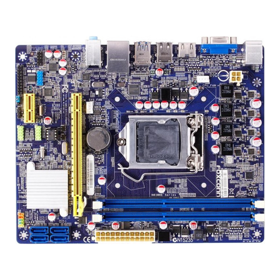
1-2 layout 1. 4-pin ATX 12V Power Connector 10. Front USB Connectors 2. SYS_FAN1 Header 11. Clear CMOS Jumper 3. PCI Express Slot PCI Express Slot 12. Front Panel Connectors 4. COM1 Connector 13. SATA Connector 14. 24-Pin ATX Power Connector 5. Front Audio Connector 15. DDR3 DIMM Slots DDR3 DIMM Slots 6. TPM Connector Connector 16. -
Page 12: Back Panel Connectors
1-3 back Panel Connectors PS/2 Mouse Port LAN Port (H61MXE-V) Line In Line Out Microphone In PS/2 Keyboard Port VGA port Audio Ports USB 2.0 Ports PS/2 Mouse Port LAN Port (H61MXE-S) Line In Line Out Microphone In PS/2 Keyboard Port VGA port HDMI port USB 2.0 Ports USB 3.0 Ports Audio Ports... - Page 13 5. HDMI Port The HDMI (High-Definition Multimedia Interface) provides an all-digital audio/video interface to transmit the uncompressed audio/video signals and is HDCP compliant. Connect the HDMI audio/ video device to this port. The HDMI Technology can support a maximum resolution of 1920x1080p but the actual resolutions supported depend on the monitor being used. 6. USb 3.0 Ports The USB port supports the USB 3.0/2.0/1.1 specification. Use this port for USB devices such as an USB keyboard/mouse, USB printer, USB flash drive and etc. You need to install the USB 3.0 driver in the Driver CD before using it. 7.
- Page 14 This chapter introduces the hardware installation process, includ- ing the installation of the CPU, memory, power supply, slots, pin headers and the mounting of jumpers. Caution should be exercised during the installation of these modules. Please refer to the moth- erboard layout prior to any installation and read the contents in this chapter carefully.
-
Page 15: Install The Cpu And Cpu Cooler
2-1 Install the CPU and CPU Cooler Read the following guidelines before you begin to install the CPU : ■ Make sure that the motherboard supports the CPU. ■ Always turn off the computer and unplug the power cord from the power supply before installing the CPU to prevent hardware damage. ■ Locate the pin one of the CPU. The CPU cannot be inserted if oriented incorrectly. (Or you may locate the notches on both sides of the CPU and alignment keys on the CPU socket.) ■ Apply an even and thin layer of thermal grease on the surface of the CPU. - Page 16 Follow the steps to install the CPU onto the CPU socket : Before installing the CPU, make sure to turn off the computer and unplug the power cord from the power outlet to prevent damage to the CPU. 1. Release the CPU socket lever. Release the CPU socket lever.
-
Page 17: Install The Cpu Cooler
Install the CPU Cooler Follow the steps below to correctly install the CPU cooler on the motherboard. 1. Apply and spread an even ther- 2. Place the four bolts of the CPU mal grease on the surface of CPU. cooler to the holes of the mother- board, push them straight down from the top, and the bolts will be fas- tened on the motherboard. -
Page 18: Install The Memory
2-2 Install the Memory Read the following guidelines before you begin to install the memory : ■ Make sure that the motherboard supports the memory. It is recommended that memory of the same capacity, brand, speed, and chips be used. ■ Always turn off the computer and unplug the power cord from the power outlet before installing the memory to prevent hardware damage. ■ Memory modules have a foolproof design. A memory module can be installed in only one direction. -
Page 19: Installing A Memory
Installing a Memory Before installing a memory module, make sure to turn off the computer and unplug the Before installing a memory module, make sure to turn off the computer and unplug the power cord from the power outlet to prevent damage to the memory module. Be sure to install DDR3 DIMMs on this motherboard. -
Page 20: Install An Expansion Card
2-3 Install an Expansion Card ■ Make sure the motherboard supports the expansion card. Carefully read the manual that came with your expansion card. ■ Always turn off the computer and unplug the power cord from the power outlet before installing an expansion card to prevent hardware damage. PCI Express x16 PCI Express x1 follow the steps below to correctly install your expansion card in the expansion slot. 1. -
Page 21: Install Other Internal Connectors
2-4 Install other Internal Connectors Power Connectors This motherboard uses an ATX power supply. In order not to damage any device, make sure all the devices have been installed properly before applying the power supply. 24-pin ATX Power Connector : PWR1 PWR1 is the ATX power supply connector. - Page 22 Audio Connector : f_AUDIo A_MIC2_L AUD_GND The audio connector supports HD Audio standard. It A_MIC2_R PRESENCEJ provides the Front Audio output choice. A_LINE2_R SENSE1_RETURN SENSE_SEND EMPTY SENSE2_RETURN A_LINE2_L F_AUDIO TPM Connector : TPM1 The TPM (Trusted Platform Module) provides the ability to the PC to run applications more secure and to make transactions and communication more trust- worthy.
- Page 23 front Panel Connector : fP1 This motherboard includes one connector for connecting HDD-LED PWR-LED the front panel switch and LED Indicators. RESET-SW PWR-SW Hard Disk lED Connector (HDD-lED) EMPTY Connect to the chassis front panel IDE indicator LED. It indicates the active status of the hard disks. This 2- pin connector is directional with +/- sign. Reset Switch (RESET-SW) Attach the connector to the Reset switch on the front panel of the case;...
-
Page 24: Jumpers
2-5 Jumpers For some features needed, users can change the jumper settings on this motherboard to modify them. This section explains how to use the various functions of this motherboard by changing the jumper settings. Users should read the following content carefully prior to modifying any jumper setting. - Page 25 Intel ME Jumper: PCH_ME_ENAblE ® This motherboard uses PCH_ME_ENABLE jumper to enable or disable Intel® Management Engine function. Intel® Management Engine (ME) is an embedded microcontroller located in Intel chipset. It provides latest IT management features such as Intel® AMT, that allows to improve management of corporate assets.
- Page 26 This chapter tells how to change system settings through the BIOS Setup menus. Detailed descriptions of the BIOS param- eters are also provided. You have to run the Setup Program when the following cases occur : 1. An error message appears on the screen during the system Power On Self Test (POST) process.
-
Page 27: Chapter 3 Bios Setup
Enter bIoS Setup The BIOS is the communication bridge between hardware and software, correctly setting up the BIOS parameters is critical to maintain optimal system performance. Power on the computer, when the message "Press <DEl> to enter Setup, <f7> to boot Menu" appears at the bottom of the screen, you can press <DEL> key to enter Setup. We do not suggest that you change the default values in the BIOS Setup, and we shall not be responsible for any damage which resulted from the change you made. -
Page 28: Main
Main Aptio Setup Utility - Copyright (C) 2010 American Megatrends, Inc. Main Advanced Chipset Boot Security Save & Exit Main BIOS Information Set the Date. Use Tab to BIOS Vendor American Megatrends switch between Date elements. Core Version 4.6.5.1 BIOS Version BB3F1D06 Build Date and Time 12/16/2011 18:45:43 Model Name H61MXE ME FW Version 8.0.0.1351 Total Memory 2048 MB (DDR3) MAC Address 0C-EO-4C-36-40-06 System Language [English] → ← : Select Screen ↑ ↓ : Select Item System Date [Fri 01/09/2009] Enter: Select System Time [15:09:21] +/-: Change Opt. - Page 29 ► Build Date and Time This item shows the BIOS building date and time. ► CPU Brand Name It displays the current CPU name. ► Total Memory This item displays the total memory size. The size is depending on how many memory mod- ules are installed in your system before powering on.
-
Page 30: Advanced
Advance Aptio Setup Utility - Copyright (C) 2011 American Megatrends, Inc. Main Advanced Chipset Boot Security Save & Exit Advanced System Super IO Chip Param- ▶ S5 RTC Wake Settings eters. ▶ CPU Configuration ▶ Performance Tuning ▶ IT8772E Super IO Configuration ▶ Onboard Device Configuration ▶ Power Management ▶ SATA Configuration ▶ Health → ← : Select Screen ↑ ↓ : Select Item Enter: Select +/-: Change Opt. F1: General Help F2: Previous Values F3: Optimized Defaults F4: Save & Exit ESC: Exit Version 2.14.1219. Copyright (C) 2011 American Megatrends, Inc. ► S5 RTC Wake Settings /CPU Configuration/Performance Tuning/ IT8772E Super IO Con- figuration/Onboard Device Configuration/Power Management/SATA Configuration/Health S5 RTC Wake Settings Aptio Setup Utility - Copyright (C) 2011 American Megatrends, Inc. -
Page 31: Cpu Configuration
CPU Configuration Aptio Setup Utility - Copyright (C) 2011 American Megatrends, Inc. F-Center Advance Number of cores to enable in CPU Configuration each processor package, Genuine Intel(R) CPU @ 1.80GHz CPU Signature 306a4 Microcode Patch Max CPU Speed 1800 MHz Min CPU Speed 1600 MHz CPU Speed 1800MHz Processor Cores Intel HT Technolony Not Supported Intel VT-x Technolony Supported Intel SMX Technolony Supported 64-bit Supported → ← : Select Screen L1 Data Cache 32 KB x 4 ↑ ↓ : Select Item L1 Code Cache 32 KB x 4 Enter: Select L2 Cache... -
Page 32: Performance Tuning
► Adjacent Cache Line Prefetch (Appears only when CPU supports) The processor has a hardware adjacent cache line prefetch mechanism that automatically fetches an extra 64-byte cache line whenever the processor requests for a 64-byte cache line. This reduces cache latency by making the next cache line immediately available if the proces- sor requires it as well. When enabled, the processor will retrieve the currently requested cache line, as well as the subsequent cache line. -
Page 33: Turbo Mode
►Turbo Mode Turbo mode allows processor cores to run faster than its marked frequency in specific condi- tion. ► Performance Memory Profiles This item is used to select performance memory profile. Options:[Automatic], [Manual], [XMP Profile 1], [XMP Profile 2]. [Automatic]- Configuration database of using performance memory profile. [Manual]- Configuration database of using performance memory profile. The next submenu will apear when select this item. [XMP Profile 1]-Configuration database of using XMP timing profile 1. [XMP Profile 2]- Configuration database of using XMP timing profile 2. IT8772E Super IO Configuration Aptio Setup Utility - Copyright (C) 2011 American Megatrends, Inc. Advanced Set Parameeters of Series Port IT8772E Super IO Configuration O (COMA) IT8772E Super IO Chip IT8772E ► Series Port O Configuration → ←... -
Page 34: Onboard Device Configuration
Onboard Device Configuration Aptio Setup Utility - Copyright (C) 2011 American Megatrends, Inc. Advanced Onboard Device Configuration Onboard LAN Controller [Enabled] Onboard LAN PXE OpROM [Disabled] intel HD Audio [Auto] → ← : Select Screen ↑ ↓ : Select Item Enter: Select +/-: Change Opt. F1: General Help F2: Previous Values F3: Optimized Defaults F4: Save & Exit ESC: Exit Version 2.142.1219. Copyright (C) 2010 American Megatrends, Inc. ► Onboard LAN Controller This item is used to enable or disable the onboard LAN controller. ►... -
Page 35: Power Management
Power Management Aptio Setup Utility - Copyright (C) 2011 American Megatrends, Inc. Advanced Enable ACPI Auto Configuration [Disabled] Enables or Disables BIOS ACPI Enable Hibernation [Enabled] Auto Configuration. ACPI Sleep State [S3] Resume By PS2 KB/Mouse [Enabled] Resume By Onboard LAN [Disabled] Resume By USB Device(s) [Enabled] Resume By PCIE PME [Disabled] DeepSx Mode [Disabled] Restore AC Power Loss [Last State] → ← : Select Screen ↑ ↓ : Select Item Enter: Select +/-: Change Opt. F1: General Help F2: Previous Values F3: Optimized Defaults F4: Save & Exit ESC: Exit... -
Page 36: Sata Configuration
SATA Configuration Aptio Setup Utility - Copyright (C) 2011 American Megatrends, Inc. Advanced SATA Configuration Enables or Disables SATA Device. SATA Controller(s) [Enabled] SATA Mode Selection [AHCI] SATA Port1 Empty SATA Port2 Empty SATA Port3 Empty SATA Port4 Empty → ← : Select Screen ↑ ↓ : Select Item Enter: Select +/-: Change Opt. F1: General Help F2: Previous Values F3: Optimized Defaults F4: Save & Exit ESC: Exit Version 2.14.1219. Copyright (C) 2011 American Megatrends, Inc. ► SATA Controller This item is used to enable or disable the onboard SATA controller. -
Page 37: Health
Health Aptio Setup Utility - Copyright (C) 2011 American Megatrends, Inc. Advanced Case Open Warning [Disabled] Enabled Case Open Warning and Smart Fan Function [Enabled] open chassis,Intrusion Alarm will appear. If don’t enter CPU Temperature : 35 C bios setup and disabled Case System Temperature : +39 C Open Warning one time, Instru- Fan1 Speed : 3.86 RPM sion Alarm don’t clear,it will Fan2 Speed : N/A appear all the time. V_CPU_CORE : +0.960 V V_SM : +1.656 V 12V_SYS : +12.201 V 5V_SYS : +12.201 V 5V_DUAL : +5.160 V VSB3 : +3.336 V → ← : Select Screen VBAT : +3.024 V ↑ ↓... -
Page 38: Chipset
Chipset Aptio Setup Utility - Copyright (C) 2011 American Megatrends, Inc. Main Advanced Chipset Boot Security Save & Exit Chipset Select which of IGFX/PEG/PCI Chipset Configuration Graphics devices should be Pri- mary Display or select SG for Primary Display [Auto] Switchable Gfx. Internal Graphics [Auto] IGD Memory [256M] → ← : Select Screen ↑ ↓ : Select Item Enter: Select +/-: Change Opt. F1: General Help F2: Previous Values F3: Optimized Defaults F4: Save & Exit ESC: Exit Version 2.14.1219. Copyright (C) 2011 American Megatrends, Inc. ►... -
Page 39: Boot
boot Aptio Setup Utility - Copyright (C) 2011 American Megatrends, Inc. Boot Main Advanced Chipset Security Save & Exit Boot Configuration Select the keyboard NumLock Bootup Numlock State [On] state Quiet Boot [Enabled] Fast Boot Fast Boot [Disabled] [Disabled] [Disabled] UEFI Boot [Disabled] Set Boot Priority 1st Boot [CD/DVD] 2nd Boot [Hard Disk] 3rd Boot [USB KEY] 4th Boot [USB Floppy] → ← : Select Screen 5th Boot [USB CD/DVD] ↑ ↓ : Select Item 6th Boot [USB Hard Disk] Enter: Select... -
Page 40: Security
Security Aptio Setup Utility - C opyright (C) 2011 American Megatrends, Inc. Main Advanced Chipset Boot Save & Exit Security Set User Password. Password Description If ONLY the Administrator’s password is set, then this only limits access to Setup and is only asked for when entering Setup. If ONLY the User’s password is set, then this is a power on password and must be entered to boot or enter Setup. In Setup the User will have Administrator rights. The password must be in the following range: Minimum length 3 → ← : Select Screen Maximum length 20 ↑ ↓ : Select Item Enter: Select +/-: Change Opt. Administrator Password F1: General Help User Password F2: Previous Values F3: Optimized Defaults F4: Save & Exit ESC: Exit Version 2.14.1219. Copyright (C) 2011 American Megatrends, Inc. -
Page 41: Save & Exit
Save & Exit Aptio Setup Utility - C opyright (C) 2011 American Megatrends, Inc. Save & Exit Main Advance Chipset Boot Security Reset s ystem s etup a fter s aving Save Changes and Reset the changes. Discard Changes and Reset Restore Defaults Boot Override → ← : Select Screen ↑ ↓... - Page 42 The utility CD that came with the motherboard contains useful software and several utility drivers that enhance the motherboard features. This chapter includes the following information: ■ Install driver and utility ■ FOX ONE ■ FOX LiveUpdate ■ FOX LOGO ■ FOX DMI ■ SmartCharger Note : Because each module is independent, so the section number will be reorganized and unique to each module, please understand.
-
Page 43: Install Driver And Utility
Manual Installation Step by Step Automatic Installa- tion by One Click Drop to System Tray Exit the program Visit Foxconn's Show Utilities Show Drivers Browse CD View the User’s Manual Website Choose the items you want to Install... - Page 44 2. Utility Use these options to install additional software programs. And click “User’s Manual“ button to view the product manual. The Driver and Utility items displayed above represent a Windows 7 based system. The appearance may change with different Operating Systems.
-
Page 45: Fox One
foX oNE FOX ONE is a powerful utility for easily modifying system settings. It also allows users to monitor various temperature values, voltage values, frequencies and fan speeds at any time. With FOX ONE, you can : ■ Modify system performance settings, such as the CPU and memory bus speeds, CPU voltages, fan speeds, and other system performance options. ■ Monitor hardware temperatures, voltages, frequencies and fan speeds. -
Page 46: Main Page
1. Main Page Show CPU Toolbar Information Alert Lamp Switch Button Skin Button Exit Minimum Configuration Homepage Monitor Frequency/Voltage/Fan speed/Temperature value Toolbar Use the toolbar to navigate to other pages. Alert lamp When the system is in healthy state, the color of alert lamp is green. When the system is in abnormal state, the alert lamp color is red. - Page 47 Click this button to exit the program. Minimum Click this button to drop the FOX ONE to Windows system tray located at the lower right corner of your screen. Homepage Click this button to visit Foxconn motherboard website : http://www.foxconnchannel.com...
- Page 48 Configuration This menu allows you to configure : 1). Monitor interval (ms) : This is to define the interval of different messages of system settings which are to which are to are to be displayed on Simple Mode screen. Minimum value is 1 second. 2). Simple Mode : To select which message of system settings are to be displayed in the Simple Mode.
- Page 49 Step 1 : Click Calibration icon, a message pops out to ask for continue. Select Yes. Step 2 : After data is collected, it will ask you to restart your computer now. Later on, when the FOX ONE program is activated, and F.I.S. feature (in CPU Page) is also enabled, FOX ONE will automatically adjust your CPU clock according to your system loadings.
-
Page 50: Cpu Control
2. CPU Page - CPU Control This page lets you select (or overclock) CPU clock to meet the current performance level of the system. The fastest and suitable CPU clock running for current system can be calculated by FOX ONE automatically or manually input by yourselves. Manual : You can press the up/down button to adjust your CPU clock. - Page 51 You can see the system is raising CPU clock until the system hangs. Push RESET button on the front panel of your system to restart the computer. Run FOX ONE program again, it will inform you the previous test found that 255MHz is the recommended CPU clock for your system.
-
Page 52: Frequency Control
FOX Intelligent Stepping (F.I.S., Optional) Select FOX Intelligent Stepping will allow your system to automatically adjust your CPU clock rate based on different system loadings. For example, if you select Power Gaming, CPU clock will be driven to run at its maximum speed. While in Energy Saving, CPU will lower down its speed to a minimum. -
Page 53: Limit Setting
4. Limit Setting 4.1 Limit Setting - CPU Temperature This page lets you to set CPU high limit temperature and enable the alert function. Go to Limit Show current CPU Setting page temperature value Enable alert function when the CPU temperature is higher than high limit value Show current high... - Page 54 4.3 Limit Setting - CPU Fan This page lets you to set CPU fan low limit rpm and enable the alert function. Show current CPU fan rpm value Enable alert function when the CPU fan runs slower than the low limit rpm value Show current low limit rpm value of CPU fan...
-
Page 55: Voltage Control
4.5 Limit Setting - FAN1 Fan This page lets you to set FAN1 fan low limit rpm and enable the alert function. Show current FAN1 fan rpm value Enable alert function when the FAN1 fan runs slower than low limit rpm value Show current low limit rpm value of FAN1 fan Set low limit rpm by... -
Page 56: Fan Control
6. Fan Page - Fan Control This page lets you enable Smart Fan function or set the fan speed by manual. When Smart Fan is selected, you must use a 4-pin CPU cooler in your system. Go to Fan page Enable or disable smart fan function Set fan speed by dragging the lever Apply the changes... -
Page 57: Fox Liveupdate
FOX LiveUpdate FOX LiveUpdate is a useful utility to backup and update your system BIOS, drivers and utilities by local or online. Supporting Operating Systems : ■ Windows XP (32-bit and 64-bit) ■ Windows 7 (32-bit and 64-bit) Please set the BIOS setting “BIOS Write Protect” or “Super BIOS Protect” to [Disabled] when running this application. - Page 58 1-2 local Update - backup This page can backup your system BIOS. You can click “Backup”, and key in a file name, then click “Save” to finish the backup operation. The extension of this backup file is ".BIN" for Award BIOS and ".ROM" for AMI BIOS. Default directory is "C:\Desktop\My Documents" in Windows XP and "Documents" in Vista. Make sure you can remember the file name together with the directory which it is stored, prevented that you may need them to recover your BIOS later. Key in a BIOS name Click here 1-3 local Update - Update This page helps you to update your BIOS from a local file. After click “Update”, An alert message will be displayed to ensure if you really want to continue, click “Yes” to confirm. A setup wizard will guide you to load a local BIOS file to finish the operation. You must remember from which directory to load your new BIOS file (with an extension of ".BIN" for Award BIOS, ".ROM" for AMI BIOS) before the setup wizard starts. FOX LiveUpdate can automatically backup old BIOS before update.
-
Page 59: Online Update
2. online Update 2-1 online Update - Update bIoS This page lets you update your system BIOS from Internet. Click “start”, it will search the new BIOS from Internet. Then follow the wizard to finish the update operation. Click here Current information Search new BIOS from Internet Select BIOS to update Browse detailed information Update BIOS... - Page 60 Select the driver to update Browse detailed information Install the selected driver Close the window 2-3 online Update - Update Utility This page lets you update utilities from Internet. Click “start”, it will search the new utilities from Internet. Then follow the wizard to finish the update operation. Click here Current information Search new utilities from Internet...
- Page 61 2-4 online Update - Update All This page lets you update your system drivers from Internet. Click “start”, it will search all new BIOS/drivers/utilities from Internet. Then follow the wizard to finish the update operation. Click here Current information Search all new BIOS/ drivers/utilities from Internet Browse detailed BIOS information Browse detailed driver information Browse detailed utility information...
- Page 62 3. Configure 3-1 Configure - option This page lets you set auto search options. After you enable the auto search function, FOX LiveUpdate will start its searching from Internet and if any qualified item found, it will pop out a message on the task bar to inform you to do the next step. Click here Set auto search options Set auto search the latest...
- Page 63 When you enable "Auto Search FOX LiveUpdate", if your FOX LiveUpdate version is older, it will auto search from internet and prompt you to install the new version. Prompt you to install the new FOX LiveUpdate 3-2 Configure - System This page lets you set the backup BIOS location and determine if the FOX LiveUpdate can auto determine if the FOX LiveUpdate can auto run when the system starts up.
-
Page 64: Configure
3-3 Configure - Advance This page lets you select to flash BIOS / Boot Block and clear CMOS. If you choose Flash Boot Block, it means BIOS is not protective, and you must make sure the flash process is continuous and without any interruption. Click here Select which BIOS ROM to flash(Only available to motherboard with backup BIOS ROM ) Select to flash Boot Block Select to clear CMOS Apply the changes Reset to default value We recommend that you had better keep the default setting unchanged to avoid any damage. -
Page 65: Fox Logo
foX loGo FOX LOGO is a simple and useful utility to backup, change and delete the boot time Logo. The boot Logo is the image that appears on screen during POST (Power-On Self-Test). You can prepare a JPG image (1024x768) file, then use FOX LOGO to open it and change the boot time Logo. Boot time Logo will be displayed if you enable the BIOS "Quiet Boot" setting in "Advanced BIOS Features" menu. -
Page 66: Fox Dmi
foX DMI FOX DMI is a full Desktop Management Interface viewer, and it provides three DMI data formats : Report, Data Fields and Memory Dump. With DMI information, system maker can easily analyze and troubleshoot your mother- board if there is any problem occurred. Supporting Operating Systems : ■ Windows XP (32-bit and 64-bit) ■ Windows 7 (32-bit and 64-bit)
Need help?
Do you have a question about the H61MXE Series and is the answer not in the manual?
Questions and answers