
Related Manuals for GE Zenith Controls ZBTS


Summary of Contents for GE Zenith Controls ZBTS
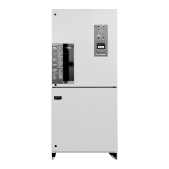
- Page 1 71R-4000B 1/06 GE Zenith Controls ZBTS/ZBTSD Series Bypass Isolation Transfer Switches 100-4000 Amps Operation and Maintenance Manual...
-
Page 2: Table Of Contents
1600-4000 Amps ..... . . Introduction GE Zenith Transfer Switches are used to provide a continuous source of power for lighting and other critical loads by auto- matically transferring from source 1 power to source 2 power in the event that source 1 voltage falls below preset limits. -
Page 3: Safety
Safety (Can Cause Severe Injury or Death) Turn OFF all power before installation, adjustment, or removal of transfer switch or any of its components. The safe operation of your switch is GE Zenith’s focus. The proper storage, installation, operation and mainte- nance will help increase the life of the switch. -
Page 4: Installation
Installation (Can Cause Severe Injury or Death) Turn OFF all power before installation, adjustment, or removal of transfer switch or any of its components. Power Connections GE Zenith transfer switches are supplied with UL listed solderless screw type terminals as standard for the Source 1, Source 2 and Load power connections. - Page 5 Installation (cont’d) (Can Cause Severe Injury or Death) Turn OFF all power before installation, adjustment, or removal of transfer switch or any of its components. P Relay (Engine Start) Figure 2 Engine Start Control Connections The engine-start terminals are clearly identified by a label on the microcontroller backplate.
-
Page 6: Initial Energization
M O N 2 3 A P R 2 0 0 2 M O R E T E S T Figure 5 – LCD and keypad ZBTS / ZBTSD Operation and Maintenance Manual (71R-4000A) Unlock the enclosure. Open the enclosure. Place the Disconnect Switch in the Inhibit. -
Page 7: Control Connections
Installation (cont’d) (Can Cause Severe Injury or Death) Turn OFF all power before installation, adjustment, or removal of transfer switch or any of its components. Control Connections Figure 6 Engine Start Connections Input/Output Connectors to I/O Modules A complete information package is furnished with... -
Page 8: Entelli-Switch 250 Microprocessor Controller
II. The Controls Power Supply (CPS) Contains transformers which drop line voltage to control level for controller input and SCR inputs (see figure 7). ZBTS / ZBTSD Operation and Maintenance Manual (71R-4000A) Engine Start Relay P I/O Interface Figure 7... -
Page 9: Lcd & Keypad
GE Zenith Controls ZBTS / ZBTSD Operation and Maintenance Manual (71R-4000A) no changes can be made without entry of the access code. The factory set six-digit access code is located on a white label on the back of the unit (see figure 11 pgs. -
Page 10: User Setting For Voltage & Frequency
Adjust via the SET menu. Range is 85% to 100% in 1% increments (see page 17). Once satisfied, the W timer will begin timing to transfer to Source 2. ZBTS / ZBTSD Operation and Maintenance Manual (71R-4000A) Under Voltage "Fail" Factory Default: 80% This adjustment determines the low voltage threshold. -
Page 11: Accessory Group Packages
Optional Accessory. Can not be used with accessory having the same symbol. Denotes an Accessory with 2 circuits as a standard. Denotes an Accessory with 3 circuits as a standard. GE Zenith Controls ZBTS / ZBTSD Operation and Maintenance Manual (71R-4000A) Group Packages STDS EXES... -
Page 12: Accessory Definitions
Can be configured by end user for 1, 7, 14, 28, 365 day cycle. (See page 16) ZBTS / ZBTSD Operation and Maintenance Manual (71R-4000A) Load or NO-Load. One event exerciser with adjustable Engine exercise timer. Exercise duration can be set between 5 and 60 minutes in 1 minute increments. - Page 13 Q3 input to allow transfer to Source 2. To enable Q3 option, engage Q3 jumper. GE Zenith Controls ZBTS / ZBTSD Operation and Maintenance Manual (71R-4000A) (cont’d) Inhibit transfer to Source 1 circuit. Energize Q7 input to prevent transfer to Source 1.
- Page 14 T timer has timed out. The T time delay is bypassed if Source 2 fails. In "Manual", retransfer to Source 1 is upon depression of BYPASS DELAY button YEN or if Source 2 fails. ZBTS / ZBTSD Operation and Maintenance Manual (71R-4000A) (cont’d) S12P Auto / Manual Selector In "Auto"...
-
Page 15: How To Set The System Clock
10. Press SAVE (this will enter this value and move cursor to month). GE Zenith Controls ZBTS / ZBTSD Operation and Maintenance Manual (71R-4000A) (cont’d) Time Delay (S2) Source 2 Stable Timer. To delay trans- fer to Source 2. Adjustable 0-5 minutes in 1 second increments. -
Page 16: Cdt One Event Timer Exerciser
1) Press TEST 2) Press MORE 3) Press START TEST TIMER (to initiate Test). ZBTS / ZBTSD Operation and Maintenance Manual (71R-4000A) • If the CDT Exerciser is Factory configured for a Load Exerciser, the Controller will immediately start a load exercise. The controller will start the... -
Page 17: Cdp Clock Exerciser
To previous field or to exit screen. GE Zenith Controls ZBTS / ZBTSD Operation and Maintenance Manual (71R-4000A) 6. Cursor is indicated as a line under character to be changed. Change values with up and down keys. Press SAVE after each entry to save value and to move to the next value to be changed. -
Page 18: User Setup - Cfg Menu
Entelli-Switch 250 User Setup - CFG Menu ZBTS / ZBTSD Operation and Maintenance Manual (71R-4000A) Turn options ON or OFF via keypad through the CFG menu Enter six digit access code (The factory assigned six-digit access code is located on the back of the controller) WARNING Controller Inputs must be relay Isolated. -
Page 19: User Setup - Set Menu
Entelli-Switch 250 User Setup - SET Menu GE Zenith Controls ZBTS / ZBTSD Operation and Maintenance Manual (71R-4000A) Change adjustable values through the SET menu. Enter six digit access code (The factory assigned six-digit access code is located on the back of the controller) WARNING Controller Inputs must be relay Isolated. -
Page 20: User Setup - System Info
Entelli-Switch 250 User Setup - System Info ZBTS / ZBTSD Operation and Maintenance Manual (71R-4000A) View System Data Enter six digit access code (The factory assigned six-digit access code is located on the back of the controller) WARNING Controller Inputs must be relay Isolated. -
Page 21: Testing
Testing A periodic test of the transfer switch under load conditions is recommended to insure proper operation. (See National Electric Code articles 700 and 701) ATS Testing Start generator and verify proper voltage, frequency and phase sequence (match to Source 1). Shut down gen set and place in Auto. -
Page 22: Sequence Of Operation
S2 Stable Source 1 Transfer to Source 2 Fails ZBTS / ZBTSD Operation and Maintenance Manual (71R-4000A) Delayed Transition Source 1 Power Failure: When Source 1 voltage or frequency has fallen below the preset "Fail" values, the controller initiates the Time Delay Source 2 Start (Engine Start Timer "P") cycle. - Page 23 While the bypass switch is out of the AUTO position/mode, the ATS is INHIBITED from automatic operation. Make certain the ATS is left in automatic after completion of any service. GE Zenith Controls ZBTS / ZBTSD Operation and Maintenance Manual (71R-4000A) (cont’d) BYPASS SOURCE 1 SOURCE 1...
-
Page 24: Amps 1
3. Figures depict Bypass Source 1. Sequence is the same for Bypass Source 2. 4. When ATS is in Test or Isolate, Bypass Switch is manual transfer switch to either available source (indicated on light panel). 5. To operate Bypass Switch when ATS is in Test or Isolate, position MBH to available power source. - Page 25 2. Do not use excessive force on mechanical handles. 3. Figures depict Bypass Source 1. Sequence is the same for Bypass Source 2. 4. When ATS is in Test or Isolate, Bypass Switch is manual transfer switch to either available source (indicated on light panel).
- Page 26 3. Figures depict Bypass Source 1. Sequence is the same for Bypass Source 2. 4. When ATS is in Test or Isolate, Bypass Switch is a manual transfer switch to either available source (indicated on light panel). 5. To operate Bypass Switch when ATS is in Test or Isolate: a) Move MBH downward (to open Bypass Contacts BN/BE) b) Turn BSS to opposite power source.
-
Page 27: Controls Power Supply (Cps)
50/60 Hz GE Zenith Controls ZBTS / ZBTSD Operation and Maintenance Manual (71R-4000A) voltage. This is accomplished by the Controls Power Supply (CPS). This method of switching operator voltage and applying power and sensing voltage to the printed circuit board isolates the MX250 from the line voltage, further protecting the controller from harmful line transients. - Page 28 Controls Power Supply (CPS) Standard Transition CPS Schematic C.V. SCR-N Delayed Transition CPS Schematic C.V. C.V. SCR-N SCR-EO ZBTS / ZBTSD Operation and Maintenance Manual (71R-4000A) C.V. SCR-E C.V. C.V. SCR-E SCR-NO (cont’d) XN1 - SOURCE 1 CONTROL TRANSFORMER XN2 -...
-
Page 29: General Troubleshooting
Troubleshooting and Diagnostics HAZARDOUS VOLTAGES CAN CAUSE SEVERE INJURY OR DEATH. These charts may indicate problems that require authorized GE Zenith service personnel. Hazardous voltages may exist on termination plugs other than those that go into the Entelli-Switch 250. General Troubleshooting The following troubleshooting guide is used to recognize, and determine basic faults. -
Page 30: Maintenance And Testing
GE Zenith can provide complete preventative main- tenance services. Please contact the GE Zenith Technical Services Department for additional information. ZBTS / ZBTSD Operation and Maintenance Manual (71R-4000A) CDT battery replacement - lithium batteries may last up to 10 years, however it is recommended... -
Page 31: Zbtsh/Zbtsdh
GE Zenith Controls ZBTSH/ZBTSDH Operation and Maintenance Manual (71R-4000A) - Page 32 GE Zenith Controls A Product of GE Consumer & Industrial General Electric Company 830 West 40 Street, Chicago, IL 60609 USA 773 299-6600 , Fax: 630 652-4501 www.geelectrical.com...
Need help?
Do you have a question about the ZBTS and is the answer not in the manual?
Questions and answers