Table of Contents
Advertisement
Operator: Save these instructions for future use!
FAILURE TO READ AND FOLLOW ALL INSTRUCTIONS CAREFULLY
BEFORE INSTALLING OR OPERATING THIS CONTROL COULD CAUSE
PERSONAL INJURY AND/OR PROPERTY DAMAGE.
Your new White-Rodgers 5-Day/1-Day/1-Day Digital Thermo-
stat uses the technology of a solid-state microcomputer to
provide precise time/temperature control. This thermostat offers
you the flexibility to design heating and cooling programs that fit
your needs.
Features:
• Separate 5-day (weekday), 1-day (Sat) and 1-day (Sun) pro-
gramming with four separate time/temperature periods per day
• Simultaneous heat and cool program storage
• Preprogrammed temperature control
• LCD continuously displays set point, and alternately
displays time and room temperature
This thermostat is intended for use with a low voltage system; do
not use this thermostat with a line voltage system. If in doubt
about whether your wiring is millivolt, line, or low voltage, have
it inspected by a qualified heating and air conditioning contractor
or electrician.
Do not exceed the specification ratings.
All wiring must conform to local and national electrical codes and
ordinances.
This control is a precision instrument, and should be handled
carefully. Rough handling or distorting components could cause
the control to malfunction.
CAUTION
!
To prevent electrical shock and/or equipment dam-
age, disconnect electric power to system at main fuse
or circuit breaker box until installation is complete.
ELECTRICAL DATA
Electrical Rating:
20 to 30 VAC 50/60 Hz. or D.C.
0.05 to 1.5 Amps (Load per terminal)
1.5 Amps Maximum Total Load (All terminals combined)
THERMAL DATA
Setpoint Temperature Range:
45 F to 90 F (7 C to 32 C)
Operating Ambient Temperature Range:
32 F to 105 F
Operating Humidity Range:
0 to 90% RH (non-condensing)
Shipping Temperature Range:
-4 F to 150 F
WHITE-RODGERS
EMERSON ELECTRIC CO.
9797 REAVIS ROAD
ST. LOUIS, MISSOURI 63123-5398
www.white-rodgers.com
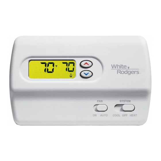
Programmable Electronic
Digital Multi-stage Thermostat
OPERATION INSTRUCTIONS
• Backlit display when any key is pushed
• Temperature override until next program period
• Manual program override (HOLD temperature)
• Temporary HOLD
•
F/ C convertibility
• Temperature range 45 to 90 F
• R, C, W, W2, G, Y and Y2 terminals
• Optional C terminal (Dual Power option)
• Program storage in case of power loss.
• 2 "AA" Energizer
Do not use on circuits exceeding specified voltage.
Higher voltage will damage control and could cause
shock or fire hazard.
Do not short out terminals on gas valve or primary
control to test. Short or incorrect wiring will damage
thermostat and could cause personal injury and/or
property damage.
Thermostat installation and all components of the
system shall conform to Class II circuits per the NEC
code.
APPLICATIONS
For use with:
• Heat/cool systems with up to two stages heat, two
stages cool
DO NOT USE WITH:
• Millivolt systems
• Systems exceeding 30 VAC and 1.5 amps
• 3-wire zoned hydronic heating systems
Printed in U.S.A.
1F81-261
INSTALLATION AND
DESCRIPTION
®
alkaline batteries included.
PRECAUTIONS
WARNING
!
SPECIFICATIONS
PART NO. 37-6228B
Replaces 37-6228A
0145
Advertisement
Table of Contents

Subscribe to Our Youtube Channel
Related Manuals for White Rodgers 1F81-261


Summary of Contents for White Rodgers 1F81-261
-
Page 1: Specifications
1F81-261 Programmable Electronic Digital Multi-stage Thermostat INSTALLATION AND OPERATION INSTRUCTIONS Operator: Save these instructions for future use! FAILURE TO READ AND FOLLOW ALL INSTRUCTIONS CAREFULLY BEFORE INSTALLING OR OPERATING THIS CONTROL COULD CAUSE PERSONAL INJURY AND/OR PROPERTY DAMAGE. DESCRIPTION Your new White-Rodgers 5-Day/1-Day/1-Day Digital Thermo- •... -
Page 2: Check Thermostat Operation
INSTALLATION REMOVE OLD THERMOSTAT Screw anchors 1. Shut off electricity at the main fuse box until installation is complete. Ensure that electrical power is disconnected. 2. Remove the front cover of the old thermostat. With wires still attached, remove wall plate from the wall. If the old thermostat has a wall mounting plate, remove the thermostat and the wall mounting plate as an assembly. -
Page 3: Wiring
NOTE NOTE The following wiring diagrams show typical terminal identifica- Relay contacts shown are thermostatically operated. tion and wiring. For proper installation, refer to the original manufacturer's instructions. * The 24 Volt neutral connection to terminal C on the thermostat is not required if you replace Thermostat the batteries once a year with... -
Page 4: Display
Heating System Cooling System 1. Move SYSTEM switch to HEAT position. If the heating CAUTION system has a standing pilot, be sure to light it. To prevent compressor and/or property damage, if the 2. Press to adjust thermostat setting above room tempera- outdoor temperature is below 50 F, DO NOT operate ture. - Page 5 Configuration Menu Step Press Button(s) Displayed (Factory Default) Press to select: COMMENTS HOLD 0 to 8 hrs (in Select temporary Hold time PRGM (0:00) 15 minute increments) and RUN Select FA or SL (Fast or Slow) heating cycle rate HOLD* (FA) Select display backlight OFF or ON HOLD*...
-
Page 6: Programming Your Thermostat
MANUAL OPERATION PROGRAMMING YOUR THERMOSTAT • HOLD TEMPERATURE — With the SYSTEM switch set to This section will help you plan your thermostat’s program to HEAT or COOL, momentarily press HOLD button. HOLD meet your needs. For maximum comfort and efficiency, keep the will be displayed. -
Page 7: Enter Cooling Program
10. Press PRGM once. “SU” (indicating Sunday program) will Entering Your Program appear in the display, along with the start time for the 1st Follow these steps to enter the heating and cooling programs heating period and the currently programmed temperature. you have selected. -
Page 8: Troubleshooting
TROUBLESHOOTING Symptom Possible Cause Corrective Action No Heat/No Cool/No Fan 1. Blown fuse or tripped circuit breaker. Replace fuse or reset breaker. (common problems) 2. Furnace power switch to OFF. Turn switch to ON. 3. Furnace blower compartment door or Replace door panel in proper position to engage panel loose or not properly installed.
Need help?
Do you have a question about the 1F81-261 and is the answer not in the manual?
Questions and answers