Table of Contents
Advertisement
Operator: Save these instructions for future use!
FAILURE TO READ AND FOLLOW ALL INSTRUCTIONS CAREFULLY
BEFORE INSTALLING OR OPERATING THIS CONTROL COULD CAUSE
PERSONAL INJURY AND/OR PROPERTY DAMAGE.
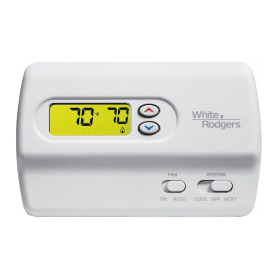
Your new White-Rodgers 5-Day/1-Day/1-Day Digital Thermostat
uses the technology of a solid-state microcomputer to provide
precise time/temperature control. This thermostat offers you
the flexibility to design heating and cooling programs that fit
your needs.
Features:
• Separate 5-day (weekday), 1-day (Sat) and 1-day (Sun) pro-
gramming with four separate time/temperature periods per
day
• Simultaneous heat and cool program storage
• Preprogrammed temperature control
• LCD continuously displays set point, and alternately
This thermostat is intended for use with a low voltage system;
do not use this thermostat with a line voltage system. If in doubt
about whether your wiring is millivolt, line, or low voltage, have
it inspected by a qualified heating and air conditioning contrac-
tor or electrician.
Do not exceed the specification ratings.
All wiring must conform to local and national electrical codes
and ordinances.
This control is a precision instrument, and should be handled
carefully. Rough handling or distorting components could cause
the control to malfunction.
CAUTION
!
To prevent electrical shock and/or equipment damage,
disconnect electric power to system at main fuse or
circuit breaker box until installation is complete.
ELECTRICAL DATA
Electrical Rating:
20 to 30 VAC 50/60 Hz. or D.C.
0.05 to 1.5 Amps (Load per terminal)
1.5 Amps Maximum Total Load (All terminals combined)
THERMAL DATA
Setpoint Temperature Range:
45°F to 90°F (7°C to 32°C)
Operating Ambient Temperature Range:
32°F to 105°F
Operating Humidity Range:
0 to 90% RH (non-condensing)
displays time and room temperature
• Backlit display when any key is pushed
• Temperature override until next program period
• Manual program override (HOLD temperature)
• Temporary HOLD
• °F/°C convertibility
• Temperature range 45° to 90°F
• R, C, W, W2, G, Y and Y2 terminals
• Optional C terminal (Dual Power option)
• Program storage in case of power loss.
• 2 "AA" Energizer
Do not use on circuits exceeding specified voltage.
Higher voltage will damage control and could cause
shock or fire hazard.
Do not short out terminals on gas valve or primary
control to test. Short or incorrect wiring will damage
thermostat and could cause personal injury and/or
property damage.
Thermostat installation and all components of the
system shall conform to Class II circuits per the NEC
code.
Shipping Temperature Range:
-4°F to 150°F
APPLICATIONS
For use with:
• Heat/cool systems with up to two stages heat, two
stages cool
DO NOT USE WITH:
• Millivolt systems
• Systems exceeding 30 VAC and 1.5 amps
• 3-wire zoned hydronic heating systems
www.white-rodgers.com
www.emersonclimate.com
1F81-261
Programmable Electronic
Digital Multi-stage Thermostat
INSTALLATION AND
OPERATION INSTRUCTIONS
DESCRIPTION
alkaline batteries included.
®
PRECAUTIONS
WARNING
!
SPECIFICATIONS
PART NO. 37-6228C
Replaces 37-6228B
1
1011
Advertisement
Table of Contents

Subscribe to Our Youtube Channel
Related Manuals for White Rodgers 1F81-261


Summary of Contents for White Rodgers 1F81-261
-
Page 1: Specifications
1F81-261 Programmable Electronic Digital Multi-stage Thermostat INSTALLATION AND OPERATION INSTRUCTIONS Operator: Save these instructions for future use! FAILURE TO READ AND FOLLOW ALL INSTRUCTIONS CAREFULLY BEFORE INSTALLING OR OPERATING THIS CONTROL COULD CAUSE PERSONAL INJURY AND/OR PROPERTY DAMAGE. DESCRIPTION Your new White-Rodgers 5-Day/1-Day/1-Day Digital Thermostat... -
Page 2: Installation
INSTALLATION REMOVE OLD THERMOSTAT Screw anchors 1. Shut off electricity at the main fuse box until installation is complete. Ensure that electrical power is disconnected. 2. Remove the front cover of the old thermostat. With wires still attached, remove wall plate from the wall. If the old thermostat has a wall mounting plate, remove the thermostat and the wall mounting plate as an assembly. -
Page 3: Wiring
WIRING NOTE NOTE Relay contacts shown are thermostatically operated. The following wiring diagrams show typical terminal identifi- cation and wiring. For proper installation, refer to the original manufacturer's instructions. * The 24 Volt neutral connection to terminal C on the thermostat is not required if you replace Thermostat the batteries once a year with... -
Page 4: Check Thermostat Operation
CHECK THERMOSTAT OPERATION Cooling System If at any time during testing your system does not operate properly, contact a qualified service person. CAUTION Turn on power to the system. To prevent compressor and/or property damage, if the Fan Operation outdoor temperature is below 50°F, DO NOT operate the cooling system. -
Page 5: Installer/Configuration Menu
INSTALLER/CONFIGURATION MENU CONFIGURATION MENU The configuration menu table summarizes the configuration options. An explanation of each option follows. The configuration menu allows you to set certain thermostat operat- Press HOLD to change to the next menu item or press TIME ing characteristics to your system or personal requirements. -
Page 6: Operation And Programming
INSTALLER/CONFIGURATION MENU loses power. It will also wait 5 minutes minimum between but you have the option to change the display temperature cooling cycles. This is intended to help protect the compres- to match your previous thermostat. sor from short cycling. Some newer compressors already 8) Select F°... -
Page 7: Entering Your Program
OPERATION AND PROGRAMMING Entering Your Program 5. Press PRGM once.The currently programmed start time and setpoint temperature for the 2nd heating program period will Follow these steps to enter the heating and cooling programs appear. you have selected. 6. Repeat steps 3 and 4 to select the start time and heating temperature for the 2nd heating program period. -
Page 8: Troubleshooting
TROUBLESHOOTING Reset Operation the thermostat has power, has been reset and still does not If a voltage spike or static discharge blanks out the display or function correctly contact your heating/cooling service person causes erratic thermostat operation you can reset the thermostat or place of purchase.
Need help?
Do you have a question about the 1F81-261 and is the answer not in the manual?
Questions and answers