Table of Contents
Advertisement
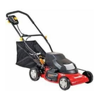
OPERATOR'S MANUAL
20 in. 24 VOLT
CORDLESS LAWN MOWER
UT13122
Your lawn mower has been engineered and manufactured to our high standard for dependability, ease of operation, and
operator safety. Properly cared for, it will give you years of rugged, trouble-free performance.
WARNING:
using this product.
Thank you for your purchase.
SAVE THIS MANUAL FOR FUTURE REFERENCE
To reduce the risk of injury, the user must read and understand the operator's manual before
Advertisement
Table of Contents


Need help?
Do you have a question about the UT13122 and is the answer not in the manual?
Questions and answers