Table of Contents
Advertisement
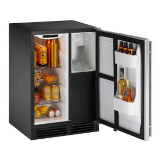
INSTALLATION GUIDE
CLEAR ICE, CLEAR ICE COMBO & ICE COMBO MODELS
CLEAR ICE
MODELS
U-CLR2160B-00
U-CLR2160B-40
U-CLR2160S-00
U-CLR2160S-01
U-CLR2160S-40
U-CLR2160S-41
U-CLR2160SOD-00
U-CLR2160SOD-01
U-CLR2160SOD-40
U-CLR2160SOD-41
U-CLR2160W-00
U-CLR2160W-40
The American Built-In Undercounter Leader Since 1962
CLEAR ICE
COMBO® MODELS
U-CLRCO2175B-00
U-CLRCO2175B-40
U-CLRCO2175S-00
U-CLRCO2175S-01
U-CLRCO2175S-40
U-CLRCO2175S-41
®
ICE COMBO®
MODELS
U-CO1175B-00
U-CO1175B-20
U-CO1175S-00
U-CO1175S-01
U-CO1175S-20
U-CO1175S-22
U-CO2175FB-00
U-CO2175FS-00
U-CO2175FS-01
U-CO2175FW-00
U-CO29B-00
U-CO29B-03
U-CO29B-20
U-CO29BTP-20
U-CO29FB-00
U-CO29FB-98
U-CO29FB-99
U-CO29FWH-00
U-CO29WH-03
U-CO29WHTP-20
U-LINE.COM
Advertisement
Table of Contents

Related Manuals for U-Line U-CLR2160B-00


Summary of Contents for U-Line U-CLR2160B-00
- Page 1 INSTALLATION GUIDE ® CLEAR ICE, CLEAR ICE COMBO & ICE COMBO MODELS CLEAR ICE CLEAR ICE ICE COMBO® MODELS COMBO® MODELS MODELS U-CLR2160B-00 U-CLRCO2175B-00 U-CO1175B-00 U-CLR2160B-40 U-CLRCO2175B-40 U-CO1175B-20 U-CLR2160S-00 U-CLRCO2175S-00 U-CO1175S-00 U-CLR2160S-01 U-CLRCO2175S-01 U-CO1175S-01 U-CLR2160S-40 U-CLRCO2175S-40 U-CO1175S-20 U-CLR2160S-41 U-CLRCO2175S-41 U-CO1175S-22...
-
Page 2: Table Of Contents
10 - Prepare Power Supply Electrical Specifications ............................17 Receptacle Location ............................17 11 - Prepare Plumbing Copper Water Supply Connection:.........................18 U-Line Water Hookup Kit Connection:......................19 Gravity Drain: ...............................19 Factory Installed Drain Pump..........................20 Drain Connection: ...............................21 Final Installation ..............................21 12 - Level the Unit Leveling Information............................22... -
Page 3: Safety Precautions
WARNING U-Line Corporation direct. Consult the installation guide before any installation begins. U-Line contact SHOCK HAZARD - Electrical Grounding Required. information appears on the rear cover of this guide. • Never attempt to repair or perform maintenance on •... -
Page 4: Inspect & Plan
Product Registration • 5/16" Nut Driver • Side Cutter You have received a carton containing your U-Line Clear Ice, Ice or • Copper tubing cutter Ice Combo unit with a package inside containing a Use and Care Guide, a Product Registration Card, and a water line kit. Please •... -
Page 5: Prepare Site
3 Prepare Site Filler Panel (Not Provided by U-Line) – May Be Added Above or Below Unit Your U-Line product has been designed for either free-standing or to Enclose for a Built-In Look built-in installation. When built-in, your unit does not require additional air space for top, sides, or rear. -
Page 6: Product Dimensions
34-1/8" 34-1/8" 34-1/8" 24" 3-13/16" 3-13/16" 24" 3-1/2" 23-15/16" Stainless Steel *Add 3/16" To Depth For Water Line Clearance Stainless Steel BLACK CO1175 *Add 3/4" To Depth For Water Line Clearance *Add 3/16" to Depth For Water Line Clearance u-line.com... -
Page 7: Door Swing Dimensions
5 Door Swing Dimensions CO29 All units have a zero clearance for the door to open 90°. U-Line 1/4" Min. recommends a minimum door clearance of 2" to accommodate the handle if the unit is installed next to a wall. -
Page 8: Standard Doors
The hinge plate is flipped over when it is reinstalled on the opposite side of the cabinet. Plastic Plastic Plug Hole Plug Hole Right Side Left Side Door Swing Door Swing u-line.com... - Page 9 3. Remove the plastic hinge bushing (2) and install in the corner Install grille. opposite of where it was removed. 4. Remove the U-Line nameplate (3) from door. This will reveal mounting holes for the door actuator bracket. 5. Remove door actuator (4) from door. Be sure to only remove the two screws holding the actuator to the door.
-
Page 10: Doors (Self-Closing)
1. Compare the top edge of the door (opposite the hinges) to the U-2115RS-01 U-2175WCCS-00 top edge of the cabinet and note the type (up or down) of U-2115RS-02 U-2175WCCS-02 adjustment needed. U-2115RSOD-00 U-2175WCCS-13 U-2115RSOD-01 U-2175WCCS-22 U-2115RW-00 U-CLR2160B-00 U-2115WCOL-00 U-CLR2160B-40 U-2115WCS-00 U-CLR2160S-00 U-2175BEVCOL-00 U-CLR2160S-01 U-2175BEVCOL-02 U-CLR21060S-40 U-2175BEVCOL-60 U-CLR2160S-41 U-2175BEVCS-00... -
Page 11: Reversing Black Or White Doors
1. Install the hinge just removed from the top to the BOTTOM opposite side of the cabinet (three screws) (2). 2. Remove the two door closer inserts (4) from the existing bottom hinge. 3. Install door closer inserts as shown on the new bottom hinge (4). u-line.com... -
Page 12: Reversing Stainless Steel Glass Doors
4. Hold door to keep it from falling. 5. Reinstall hinge screw pin (1) into top hinge using a Phillips Bottom Of Door screwdriver. Align and adjust the door: Align and adjust the door, see DOOR ALIGNMENT AND ADJUSTMENT on page 8. Pivot Plate Screws u-line.com... - Page 13 (three screws) (2). 2. Remove the two door closer inserts (4) from the preexisting bottom hinge. Logo Door Orientation Left Hand Hinge 3. Install door closer inserts as shown on the new bottom hinge Logo (4). u-line.com...
- Page 14 4. Hold door to keep it from falling. 5. Reinstall hinge screw pin (1) into top hinge using a Phillips screwdriver. Align and adjust the door: Align and adjust the door, see DOOR ALIGNMENT AND ADJUSTMENT on page 8. u-line.com...
-
Page 15: Door Panel Installation
2. Pull door gasket out of groove (top edge of door only). Start in the middle and pull outward, moving toward the edge . This may take some force. u-line.com... -
Page 16: Wood Grille Overlay
9 Wood Grille Overlay You may also mount your overlay to your grille using hook and loop type fasteners. U-Line recommends using 3M® Dual lock® Grille Overlay (Excludes CO1175) fasteners. To mount your overlay using a hook and loop fastener follow the instructions below. - Page 17 Grille Drawing 24 inch u-line.com...
- Page 18 Grille Drawing 15inch u-line.com...
-
Page 19: Prepare Power Supply Electrical Specifications
GFCI could be prone to nuisance tripping. However, be sure to consult your local codes. CO2175FF See below for recommended receptacle location CLR2160 & CLRCO2175 24" Preferred Location 7" Acceptable for CLR2160 Receptacle Location 24" 7" 1-1/2" Receptacle Location 1" CO29 24" 7" 1-1/2" u-line.com... -
Page 20: Prepare Plumbing
Do not kink or pinch the coiled line. 4. Locate the U-Line supplied hose fitting. Ensure the end on the copper tubing has been cut straight and is free of burrs. Slide the compression nut and ferrule onto the copper tubing as shown below. -
Page 21: U-Line Water Hookup Kit Connection
U-Line Water Hookup Kit Connection: Drain Connection: CAUTION CAUTION If your U-Line unit did not come with a factory installed Turn off water supply and disconnect electrical supply to drain pump you must use a gravity style drain connection. unit prior to attempting installation. -
Page 22: Factory Installed Drain Pump
Before installing your U-Line CLR2160 or CLRCO2175 Factory Installed Drain Pump with factory-installed U-Line P60 pump, it is extremely important to check and test all hose connections at the • If your drain line will run up to a stand pipe, disposal or spigot drain pump. -
Page 23: Drain Connection
In the event of a power outage, restricted drain or pump make certain the floor surfaces surrounding the unit failure, the failure to use the U-Line P60 drain pump could are dry at all times. result in substantial water leakage and pooling with severe and costly water damage and related consequential damages and harm. -
Page 24: Level The Unit Leveling Information
Push in, then lower shelf onto ribs. Door Shelves • First pull shelf up at a 45° angle, then straight out. • Choose new location and line up on bosses. First push straight in, then down at a 45° angle. u-line.com... -
Page 25: Installation Troubleshooting
Problem The custom overlay door was designed to align with the rest of the cabinet doors, but the unit has crept forward. Solution Make sure that the electrical cord and water supply line are not obstructing the installation. u-line.com... -
Page 26: The American Built-In Undercounter Leader Since
E-mail: onlineparts@u-line.com BUILDING ON THREE GENERATIONS OF INNOVATION For over five decades and through three generations, U-Line continues to be the leader in innovation, quality and performance in the premium built-in undercounter ice making, refrigeration and wine preservation market. U-Line has captivated those with an appreciation for the finer things with exceptional functionality, style, inspired innovation and attention to even the smallest details.