Table of Contents
Advertisement
Quick Links
Advertisement
Table of Contents

Related Manuals for U-Line UCBR552-SG01A


Summary of Contents for U-Line UCBR552-SG01A
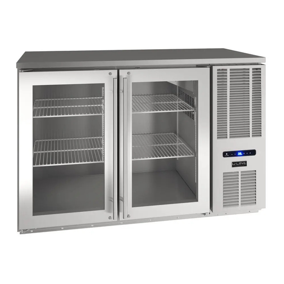
- Page 1 USER GUIDE & SERVICE MANUAL Model: UCBR552-SG01A...
-
Page 2: Table Of Contents
USER GUIDE & SERVICE MANUAL u-line.com Click on any section below to jump directly there Table of Contents Intro Warranty Claims Ordering Replacement Parts Safety R600a Specifications Safety and Warning System Diagnosis Guide Disposal And Recycling Compressor Specifications Troubleshooting Extended... - Page 3 U-Line Customer Care must be contacted immediately at +1.414.354.0300. Service or repairs performed on the unit without prior written approval from U-Line is not permitted. If the unit has been altered or repaired in the field without prior written approval from U-Line, claims will not be eligible.
-
Page 5: Disposal And Recycling
USER GUIDE u-line.com Disposal and Recycling DANGER RISK OF CHILD ENTRAPMENT. Before you throw away your old refrigerator or freezer, take off the doors and leave shelves in place so children may not easily climb inside. If the unit is being removed from service for disposal,... -
Page 6: Environmental Requirements
USER GUIDE u-line.com Environmental Requirements This unit is designed to operate between 50°F (10°C) and 100°F (38°C). Higher ambient temperatures may reduce the unit’s ability to reach low temperatures and/or reduce ice production on applicable models. For best performance, keep the unit out of direct sunlight and away from heat generating equipment. - Page 7 USER GUIDE u-line.com Electrical WARNING SHOCK HAZARD — Electrical Grounding Required. Never attempt to repair or perform maintenance on the unit until the electricity has been disconnected. Never remove the round grounding prong from the plug and never use a two-prong grounding adapter.
-
Page 8: Cutout & Product Dimensions
(813mm) 19 1/4" (489mm) PREPARE SITE Your U-Line product has been designed for either freestanding or built-in installation. When built-in, your unit does not require additional air space for top or rear. FRONT However, the front grille must NOT be obstructed, and 1-inch clearance is required for proper air flow on the 30 15/32"... - Page 9 USER GUIDE u-line.com 52" Cutout & Product Dimensions (1321mm) 19 1/4" FRONT (489mm) CUTOUT & PRODUCT DIMENSIONS - UCBR552/UCBR652 NOTE: THE HOLE CUTOUTS ON TOP SURFACE APPLY TO 34 15/32" 30 7/16" 28" THE UCBR652 ONLY AND ARE CUTOUT AT THE...
- Page 10 USER GUIDE u-line.com Cutout & Product Dimensions 72" (1829mm) 19 1/4" FRONT (489mm) CUTOUT & PRODUCT DIMENSIONS - UCBR572/UCBR672 NOTE: THE HOLE CUTOUTS ON TOP SURFACE APPLY TO 34 9/16" 30 7/16" 28" (773mm) (711mm) (878mm) THE UCBR672 ONLY AND ARE CUTOUT AT THE FACTORY.
- Page 11 USER GUIDE u-line.com Cutout & Product Dimensions 92" (2337mm) FRONT 19 1/4" (489mm) CUTOUT & PRODUCT DIMENSIONS - UCBR592/UCBR692 NOTE: 34 9/16" 30 7/16" 28" THE HOLE CUTOUTS ON TOP SURFACE APPLY TO (878mm) (773mm) (711mm) THE UCBR692 ONLY AND ARE CUTOUT AT THE FACTORY.
- Page 12 USER GUIDE u-line.com Cutout & Product Dimensions 4” 32” (102mm) DRILL AREA 15 3⁄4” 4 1⁄4” (400mm) (108mm) TAP TOWER KITS This template is to be used as reference if you want to add 8 5⁄8” your own tap tower kit.
-
Page 13: General Installation
USER GUIDE u-line.com General Installation INSTALLATION LEVELING INFORMATION Use a level to Turn to Adjust INSTALLATION TIP CAUTION General Installation... -
Page 14: Grille Installation
USER GUIDE u-line.com Grille Installation REMOVING AND INSTALLING GRILLE WARNING Disconnect electric power to the unit before removing the grille. When using the unit, the grille must be installed. Removing the grille Disconnect power to the unit. Installing the grille Connect power to unit. -
Page 15: Door Swing
USER GUIDE u-line.com Door Swing Wall 2-1/8" Min. (54 mm) 90° Door Swing Units have a zero clearance for the door to open 90°, when installed adjacent to cabinets. Stainless Steel models require 2-1/8" (54 mm) door clearance to accommodate the handle if installed next to a wall. -
Page 16: Door Adjust
USER GUIDE u-line.com Door Adjustments Remove hinge pin from top hinge using a 1/8” hex key tool. Rotate hinge pin clockwise to remove. Set aside. REVERSING THE DOOR Location of the unit may make it desirable to mount the door on the opposite side of the cabinet. - Page 17 USER GUIDE u-line.com PREPARE DOOR FOR INSTALLATION INSTALL DOOR ONTO UNIT Stand door up on bottom edge, handle side facing Note: To prevent damage and to have two hands you. free, it may be beneficial to have someone hold the door during the installation.
- Page 18 If the temperature displayed is different than selected, the unit is progressing towards the selected temperature. Time to reach set point varies based upon ambient temperature, temperature of product loaded, door openings, etc. U-Line recommends allowing the unit to reach set points before loading.
- Page 19 USER GUIDE u-line.com Control Operation CONTROL FUNCTION GUIDE FUNCTION COMMAND NOTES ON/OFF Press and release Unit will immediately turn On or OFF When the display is flashing, press Adjust Temperature Press and release adjust the set point temperature. Note: temperature displayed is the actual temperature inside unit Toggle between º...
- Page 20 USER GUIDE u-line.com Airflow and Product Loading AIRFLOW External • Do not block the front grille - no additional clearance around sides, top or rear of unit is needed for ventilation • Do not install behind a closed door Internal •...
-
Page 21: Interior Adjustments
USER GUIDE u-line.com Interior Adjustments Clips MUST be installed with the ribbed side down. Failure to do so may result in shelf or unit REMOVING AND INSTALLING SHELVES damage. NOTICE Adjusting Interior Shelves All 4 shelf clips for each shelf must be installed at Models equipped with wire rack or glass cantilever shelves the same height for shelf stability. -
Page 22: Cleaning
USER GUIDE u-line.com Cleaning CLEAN INTERIOR COMPONENTS CLEANING VS. SANITIZING Use warm or hot water with dish soap to clean all removed This guide will address both the cleaning and the sanitizing components and interior surfaces. You may use a vinegar and of the unit. - Page 23 Disassemble by unscrewing the cap. Rinse cap and filter ULACOFFEECLEAN (Stera-Sheen®) was included with your with warm potable water and reassemble. product and more can be purchased at u-line.com. Notice Confirm system is not pressurized by turning off nitrogen – turn handle clockwise. Release...
- Page 24 USER GUIDE u-line.com Cleaning the Beer-Dispensing System Clean the system using a suitable solution designed for beer- dispensing systems. Beer cleaning kits are also available. Solution and/or kit not included. Close CO tank. Pull pin on coupler to release pressure from keg.
- Page 25 USER GUIDE u-line.com Remove tap head from tower with supplied tap head wrench. Disassemble, and place all the parts in drainage bucket. 10. Add washer and attach cleaning pump connector to tower. Tighten with tap head wrench. 11. Pump all the solution through the beverage line.
- Page 26 USER GUIDE u-line.com DEFROSTING Under normal conditions this unit does not require manual defrosting. Minor frost on the rear wall or visible through the evaporator plate vents is normal and will melt during each cycle. If there is excessive build-up of 1/4” (6 mm) or more, manually defrost the unit.
- Page 28 USER GUIDE u-line.com Wine Rack Installation To remove rack from the cabinet: NOTE: WINE RACKS ARE NOT INCLUDED WITH THIS UNIT AND ARE SOLD AS ACCESSORIES ONLY. Remove any bottles stored on the rack. Grasp the front end of the rack, tilt upward and lift out of the rear shelf ladder.
-
Page 29: Service
If the unit will be exposed to temperatures of 40 F (5 C) or less, the steps above must be followed. For questions regarding winterization, please call U-Line at 414.354.0300. CAUTION Damage caused by freezing temperatures is not covered by the warranty. Extended Non-Use... -
Page 30: Troubleshooting
BEFORE CALLING FOR SERVICE • Condenser Fan: Air moving through a condenser may be heard. If you think your U-Line product is malfunctioning, read the CONTROL OPERATION section to clearly understand the • Automatic Defrost Drain Pan: Water may be heard function of the control. - Page 31 USER GUIDE u-line.com u-line.com CHECKING PRODUCT TEMPERATURE Causes which affect the internal temperatures of the cabinet include: • Temperature setting. • Ambient temperature where installed. • Installation in direct sunlight or near a heat source. • The number of door openings and the time the door is open.
-
Page 34: Product Liability
The part that caused the damage must be returned to U-Line in its entirety. The part must be clearly labeled with the serial number of the unit it was removed from, the date, and the servicer who removed the part. -
Page 35: Warranty Claims
Claims must be submitted online at • Final billing - Remodel www.U-LineService.com Warranty parts will be shipped at no charge after U-Line • 60 day submittal deadline from date of completed confirms warranty status. Please provide the model, serial service number, part number and part description. -
Page 36: Ordering Replacement Parts
Warranty parts will be shipped at no charge after U-Line confirms warranty status. Please provide the model, serial number, part number and part description. Some parts will require color or voltage information. -
Page 41: System Diagnosis Guide
USER GUIDE u-line.com System Diagnosis Guide REGRIGERATION SYSTEM DIAGNOSIS GUIDE System Suction Suction Compressor Condenser Capillary Evaporator Wattage Condition Pressure Line Discharge Tube Normal Normal Slightly Very hot Very hot Warm Cold Normal below room temperature Overcharge Higher than Very cold... -
Page 46: Control Operation-Service
USER GUIDE u-line.com Control Operation-Service CONTROL FUNCTION GUIDE FUNCTION COMMAND DISPLAY/OPTIONS UI BUTTON LAYOUT and release Unit will immediately Press ON/OFF turn ON or OFF Sabbath Mode See “Sabbath Mode” section Hidden Button SHOWROOM MODE -Access Service Menu This mode is designed to show units in a display -No LED directly above. - Page 47 USER GUIDE u-line.com SERVICE MODE GUIDE SERVICE MODE GUIDE 0. Exit THERMISTOR 1 — ZONE 1. Thermistor 1 temperature not including offsets. This shows the pure thermistor reading with no offsets 2. Thermistor 2 temperature not including offsets. taken into account.
- Page 48 USER GUIDE u-line.com E3: Thermistor 3 open. MAIN SOFTWARE E4: Thermistor 4 open (Does not apply to this model). 26. Does not apply to this model E5: Thermistor 1 shorted. 27. FACTORY TEST MODEL E6: Thermistor 2 shorted. 0 = Off, 1 = On E7: Thermistor 3 shorted.
- Page 49 MODEL NUMBER 1. Disconnect the unit from power source. 2. Push and hold the U-Line button. 3. While still holding the U-Line button, plug the unit into the appropriate power source. 4. When the flashing digits appear (3-5 seconds), use the up and down arrow buttons to select the appropriate model number*.
- Page 50 USER GUIDE u-line.com Control Operation-Service...
-
Page 51: Thermistor
USER GUIDE USER GUIDE u-line.com u-line.com Thermistors Thermistor Thermistor Resistance Data Thermistor Resistance Data Nominal Resistance Thermistors are used for various temperature readings. Temp (F) Temp (C) Thermistors are used for various temperature readings. (OHMS)* Thermistors provide reliable temperature readings using a... -
Page 52: Defrost
USER GUIDE u-line.com Defrost Outdoor units defrost every 12 hours of compressor runtime for 45 minutes. If you have verified that the unit does not have an ambient air leak, utilize the Control Operation - Service section and adjust unit to defrost... -
Page 53: Remove Fan And Cover
USER GUIDE u-line.com Remove Fan and Cover Remove the evaporator air deflector cooling baffle by sliding it out and set aside. Evaporator Fan Replacement Should the evaporator fan need to be replaced follow the steps below. Disconnect power from the unit before starting. - Page 54 USER GUIDE u-line.com NOTICE 6. Once the shaft is free of the gasket, rotate the fan assembly upward and out Fan must be oriented to pull air in through lower toward you and away from the evaporator cover vents and push air out at fan mounting bracket.
- Page 55 For products installed and used for normal residential use, material cosmetic defects are included in this warranty, with coverage limited to 60 days from the date of original purchase. All service provided by U-Line under the above warranty must be performed by a U-Line factory authorized servicer, unless otherwise specified by U-Line.
Need help?
Do you have a question about the UCBR552-SG01A and is the answer not in the manual?
Questions and answers