Advertisement
Quick Links
Advertisement

Related Manuals for U-Line UCBR592-SS01A


Summary of Contents for U-Line UCBR592-SS01A
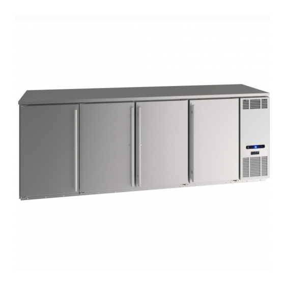
- Page 1 USER GUIDE & SERVICE MANUAL Model: UCBR592-SS01A...
- Page 2 USER GUIDE & SERVICE MANUAL Click on any section below to jump directly there Table of Contents Intro Warranty Claims Ordering Replacement Parts Safety R600a Specifications Safety and Warning System Diagnosis Guide Disposal And Recycling Compressor Specifications Troubleshooting Extended Installation Control Operation - Service Environmental Requirements Thermistor...
- Page 3 U-Line Customer Care must be contacted immediately at +1.414.354.0300. Service or repairs performed on the unit without prior written approval from U-Line is not permitted. If the unit has been altered or repaired in the field without prior written approval from U-Line, claims will not be eligible.
- Page 4 USER GUIDE Safety and Warning This appliance is not intended for use by persons (including children) with reduced physical, sensory or mental capabilities, or lack of experience or knowledge, NOTICE unless they have been given supervision or instruction Please read all instructions before installing, concerning use of the appliance by a person responsible for operating, or servicing the appliance.
- Page 5 Allow unit temperature to stabilize for 24 hours before use. Do not block any internal fans. Use only genuine U-Line replacement parts. Imitation parts can damage the unit, affect its operation or performance and may void the warranty.
- Page 6 USER GUIDE Disposal and Recycling DANGER RISK OF CHILD ENTRAPMENT. Before you throw away your old refrigerator or freezer, take off the doors and leave shelves in place so children may not easily climb inside. If the unit is being removed from service for disposal, check and obey all federal, state, and local regulations regarding the disposal and recycling of refrigeration appliances, and follow these steps completely:...
- Page 7 USER GUIDE Environmental Requirements This unit is designed to operate between 50°F (10°C) and 100°F (38°C). Higher ambient temperatures may reduce the unit’s ability to reach low temperatures and/or reduce ice production on applicable models. For best performance, keep the unit out of direct sunlight and away from heat generating equipment.
- Page 8 USER GUIDE Electrical WARNING SHOCK HAZARD — Electrical Grounding Required. Never attempt to repair or perform maintenance on the unit until the electricity has been disconnected. Never remove the round grounding prong from the plug and never use a two-prong grounding adapter.
- Page 9 USER GUIDE Cutout & Product Dimensions FRONT 92" (2337mm) 19 1/4" (489mm) CUTOUT & PRODUCT DIMENSIONS - UCBR592/UCBR692 34 9/16" (878mm) 28" 30 7/16" (711mm) (773mm) NOTE: THE HOLE CUTOUTS ON TOP SURFACE APPLY TO THE UCBR692 ONLY AND ARE CUTOUT AT THE FACTORY.
- Page 10 USER GUIDE Cutout & Product Dimensions 4” (102mm) 32” DRILL AREA 15 3⁄4” 4 1⁄4” TAP TOWER KITS (400mm) (108mm) This template is to be used as reference if you want to add your own tap tower kit. 8 5⁄8” (219mm) NOTES •...
- Page 11 USER GUIDE General Installation INSTALLATION Plug in the power/electrical cord. LEVELING INFORMATION Gently push the unit into position. Use a level to confirm the unit is Re-check the leveling, from front to back and side to level. Level should side. Make any necessary adjustments. The unit’s top 1⁄8 be placed along surface should be approximately...
- Page 12 USER GUIDE Grille Installation REMOVING AND INSTALLING GRILLE WARNING Disconnect electric power to the unit before removing the grille. When using the unit, the grille must be installed. Removing the grille Disconnect power to the unit. Remove two top screws and two bottom screws. Remove Top Screws Remove...
- Page 13 USER GUIDE Door Swing Wall 2-1/8" Min. (54 mm) 90° Door Swing Units have a zero clearance for the door to open 90°, when installed adjacent to cabinets. Stainless Steel models require 2-1/8" (54 mm) door clearance to accommodate the handle if installed next to a wall.
- Page 14 USER GUIDE Door Adjustments Remove hinge pin from top hinge using a 1/8” hex key tool. Rotate hinge pin clockwise to remove. Set aside. REVERSING THE DOOR Location of the unit may make it desirable to mount the door on the opposite side of the cabinet. The hinge hardware will be removed and reinstalled on the opposite side of the cabinet.
- Page 15 USER GUIDE PREPARE DOOR FOR INSTALLATION Take bottom hinge plate and remove closer cam with a Philips screwdriver, and reinstall closer cam on Stand door up on bottom edge, handle side facing opposite surface of bottom hinge plate. you. Remove top hinge plate by using a 5/32” hex tool to A.
- Page 16 If the temperature displayed is different than selected, the unit is progressing towards the selected temperature. Time to reach set point varies based upon ambient temperature, temperature of product loaded, door openings, etc. U-Line recommends allowing the unit to reach set points before loading.
- Page 17 USER GUIDE Control Operation CONTROL FUNCTION GUIDE FUNCTION COMMAND NOTES ON/OFF Press and release Unit will immediately turn ON or OFF When the display is flashing, press Adjust Temperature Press and release adjust the set point temperature. Note: temperature displayed is the actual temperature inside unit Toggle between Hold for 5 seconds.
- Page 18 USER GUIDE Airflow and Product Loading AIRFLOW External • Do not block the front grille • A minimum of 1” clearance is required on the grille- side of the unit. A Minimum clearance of 1” is required for proper air ow. Grille •...
- Page 19 USER GUIDE Interior Adjustments Clips MUST be installed with the ribbed side down. Failure to do so may result in shelf or unit REMOVING AND INSTALLING SHELVES damage. NOTICE Adjusting Interior Shelves All 4 shelf clips for each shelf must be installed at Models equipped with wire rack or glass cantilever shelves the same height for shelf stability.
- Page 20 USER GUIDE Cleaning CLEAN INTERIOR COMPONENTS CLEANING VS. SANITIZING Use warm or hot water with dish soap to clean all removed components and interior surfaces. You may use a vinegar and This guide will address both the cleaning and the sanitizing water solution in place of soap.
- Page 21 USER GUIDE INTERIOR CLEANING & SANITIZING NOTICE Do not use any solvent-based or abrasive cleaners. These types of cleaners may transfer taste and/or odor to the interior products and damage or discolor the interior. DEFROSTING Under normal conditions this unit does not require manual defrosting.
- Page 22 USER GUIDE Cleaning Condenser INTERVAL - EVERY SIX MONTHS To maintain operational efficiency, keep the front grille free of dust and lint, and clean the condenser when necessary. Depending on environmental conditions, more or less frequent cleaning may be necessary. WARNING Disconnect electric power to the unit before cleaning the condenser.
- Page 23 USER GUIDE Wine Rack Installation To remove rack from the cabinet: NOTE: WINE RACKS ARE NOT INCLUDED WITH THIS UNIT AND ARE SOLD AS ACCESSORIES ONLY. Remove any bottles stored on the rack. Grasp the front end of the rack, tilt upward and lift out of the rear shelf ladder.
- Page 24 If the unit will be exposed to temperatures of 40 F (5 C) or less, the steps above must be followed. For questions regarding winterization, please call U-Line at 414.354.0300. CAUTION Damage caused by freezing temperatures is not covered by the warranty. Extended Non-Use...
- Page 25 BEFORE CALLING FOR SERVICE • Condenser Fan: Air moving through a condenser may be heard. If you think your U-Line product is malfunctioning, read the CONTROL OPERATION section to clearly understand the • Automatic Defrost Drain Pan: Water may be heard function of the control.
- Page 26 USER GUIDE CHECKING PRODUCT TEMPERATURE Causes which affect the internal temperatures of the cabinet include: • Temperature setting. • Ambient temperature where installed. • Installation in direct sunlight or near a heat source. • The number of door openings and the time the door is open.
- Page 27 USER GUIDE...
- Page 28 The part that caused the damage must be returned to U-Line in its entirety. The part must be clearly labeled with the serial number of the unit it was removed from, the date, and the servicer who removed the part.
- Page 29 Claims must be submitted online at • Final billing - Remodel www.U‑LineService.com Warranty parts will be shipped at no charge after U-Line • 60 day submittal deadline from date of completed confirms warranty status. Please provide the model, serial service number, part number and part description.
- Page 30 Warranty parts will be shipped at no charge after U-Line confirms warranty status. Please provide the model, serial number, part number and part description. Some parts will require color or voltage information.
- Page 31 Never use a torch on a fully charged refrigeration system. R-600a is heavier than air, do not allow any Never substitute U-Line OEM replacement parts leakage/migration to low areas such as or methods of construction. basements and stairs. Never substitute U-Line OEM replacement parts or methods of construction.
- Page 32 USER GUIDE R290/R600a SPECIFICATIONS/LABELING WARNING R290/R600a equipped products are labeled (both the unit Only skilled and well trained service technicians and the compressor). permitted to service R290/R600a equipped products. R290/R600a is colorless and odorless. All tools and equipment must be approved for R290/R600a is considered non-toxic, but is flammable use with R290/R600a refrigerant.
- Page 33 USER GUIDE USER GUIDE u-line.com SAFETY • INSTALLATION & INTEGRATION • OPERATING INSTRUCTIONS • MAINTENANCE • SERVICE Evacuate/reclaim via the piecing pliers to ensure the When re-brazing, the system must be purged with system is empty of R290/R600a before any system work is...
- Page 34 USER GUIDE USER GUIDE u-line.com SAFETY • INSTALLATION & INTEGRATION • OPERATING INSTRUCTIONS • MAINTENANCE • SERVICE Proper ventilation during service is required. The low side of the refrigeration system (evaporator, Proper ventilation during service is required. compressor and suction line) must be leak tested with the Never apply a torch to a charged R290/R600a refrigeration compressor off (equalized pressure).
- Page 35 USER GUIDE u-line.com System Diagnosis Guide REGRIGERATION SYSTEM DIAGNOSIS GUIDE System Suction Suction Compressor Condenser Capillary Evaporator Wattage Condition Pressure Line Discharge Tube Normal Normal Slightly Very hot Very hot Warm Cold Normal below room temperature Overcharge Higher than Very cold...
- Page 36 USER GUIDE Compressor Specifications EM2X3125U REFRIGERANT R290 VOLTAGE 120 VAC DANGER FREQUENCY 60 Hz START WINDING 5 Ohm at 77 Electrocution can cause death or serious injury. RUN WINDING 3 Ohm at 77 Burns from hot or cold surfaces can cause serious RUN TO START 8 Ohm at 77 injury.
- Page 37 • Automatic Defrost Drain Pan: Water may be heard U-Line Corp, “Customer Care Facility” at +1.800.779.2547 dripping or running into the drain pan when the unit is for assistance. in the defrost cycle.
- Page 38 USER GUIDE TROUBLESHOOTING GUIDE Concern Potential Causes Action Not Cooling Compressor overheating Verify proper air flow through condenser. Is condenser clean? Confirm condenser fan operation. Compressor not operating Test overload and relay, replace as needed. Compressor operating - no cooling Refer to System Diagnosis Guide.
- Page 39 USER GUIDE MAIN CONTROL CAUTION The main control board is very robust and is rarely the cause of system issues. It is important to fully diagnose Precautions must be taken while working with the board for any suspected failures before attempting live electrical equipment.
- Page 40 USER GUIDE Control Operation-Service CONTROL FUNCTION GUIDE FUNCTION COMMAND DISPLAY/OPTIONS UI BUTTON LAYOUT and release Unit will immediately Press ON/OFF turn ON or OFF See “Cleaning” Clean Mode section See “Sabbath Mode” Sabbath Mode section Showroom Mode 1. Hidden Button This mode is designed to show units in a display •...
- Page 41 USER GUIDE USER GUIDE u-line.com Thermistor Thermistor Thermistor Resistance Data Thermistor Resistance Data Nominal Resistance Thermistors are used for various temperature readings. Temp (F) Temp (C) Thermistors are used for various temperature readings. (OHMS)* Thermistors provide reliable temperature readings using a...
- Page 42 USER GUIDE Defrost If you have verified that the unit does not have an ambient air leak, utilize the Control Operation - Service section and adjust unit to defrost longer and/or more/less often as needed. Defrost...
- Page 43 USER GUIDE Remove Fan and Cover Remove the evaporator air deflector cooling baffle by sliding it out and set aside. Evaporator Fan Replacement 1. Disconnect power from the unit before starting. Remove the front cover grille. Take out the two upper and two lower screws. Disconnect the power cord from the back of the Upper grille screws Set grille aside...
- Page 44 USER GUIDE Once the shaft is free of the gasket, rotate the fan assembly upward and out toward you and away from the mounting bracket. Installation is the reverse of removal. Take special care to properly route wires away from fans and copper tubing and make sure fan motor is secured in rubber gasket.
- Page 45 For products installed and used for normal residential use, material cosmetic defects are included in this warranty, with coverage limited to 60 days from the date of original purchase. All service provided by U-Line under the above warranty must be performed by a U-Line factory authorized servicer, unless otherwise specified by U-Line.
Need help?
Do you have a question about the UCBR592-SS01A and is the answer not in the manual?
Questions and answers