Table of Contents
Advertisement
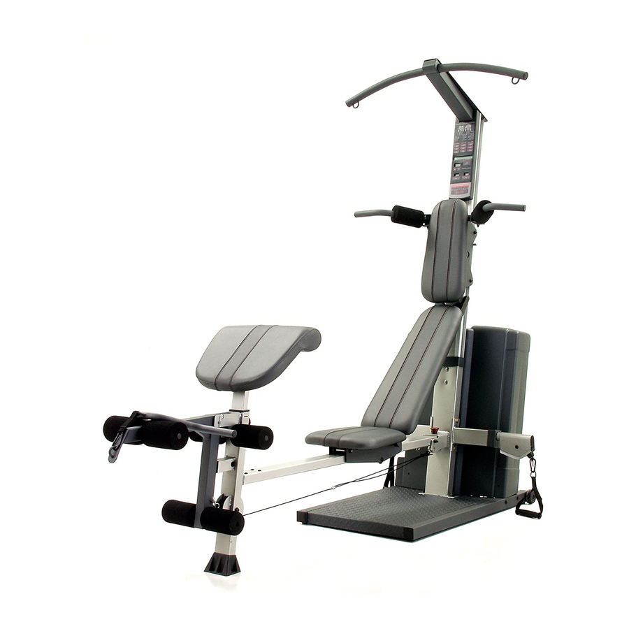
Model No. WESY9975.0
Serial No.
Write the serial number in the
space above for future reference.
Serial Number Decal (under seat)
QUESTIONS?
As a manufacturer, we are com-
mitted to providing complete
customer satisfaction. If you
have questions, or if a part is
damaged or missing, PLEASE
CONTACT OUR CUSTOMER
SERVICE DEPARTMENT
DIRECTLY.
CALL TOLL-FREE:
1-877-992-5999
Mon.–Fri., 6 a.m.–6 p.m. MST
ON THE WEB:
www.weiderservice.com
CAUTION
Read all precautions and instruc-
tions in this manual before
using this equipment. Save this
manual for future reference.
USER'S MANUAL
Visit our website at
www.weiderfitness.com
new products, prizes,
fitness tips, and much more!
Advertisement
Table of Contents

Related Manuals for Weider Platinum Plus 1000


Summary of Contents for Weider Platinum Plus 1000
- Page 1 Model No. WESY9975.0 Serial No. Write the serial number in the space above for future reference. Serial Number Decal (under seat) QUESTIONS? As a manufacturer, we are com- mitted to providing complete customer satisfaction. If you have questions, or if a part is damaged or missing, PLEASE CONTACT OUR CUSTOMER SERVICE DEPARTMENT...
-
Page 2: Table Of Contents
Note: A PART IDENTIFICATION CHART and a PART LIST/EXPLODED DRAWING are attached in the center of this manual. Remove the PART IDENTIFICATION CHART and PART LIST/EXPLODED DRAWING before begin- ning assembly. WEIDER is a registered trademark of ICON IP, Inc. -
Page 3: Warning Decal Placement
WARNING DECAL PLACEMENT The decals shown here have been placed on the resistance system. If a decal is missing or illegible, please call the toll-free telephone number on the front cover of this manual and order a free replacement decal. Apply the decal in the location shown. -
Page 4: Important Precautions
IMPORTANT PRECAUTIONS WARNING: To reduce the risk of serious injury, read the following important precautions before using the resistance system. 1. Read all instructions in this manual and all 11. Pull on the lower cable only while sitting on warnings on the resistance system before the bench or standing on the base plate. -
Page 5: Before You Begin
BEFORE YOU BEGIN Thank you for selecting the innovative PLATINUM manual. To help us assist you, please note the product PLUS 1000 BY WEIDER ® resistance system. The model number and serial number before calling. The resistance system offers a selection of stations model number is WESY9975.0. -
Page 6: Assembly
ASSEMBLY • Tighten all parts as you assemble them, unless Make Things Easier for Yourself instructed to do otherwise. This manual is designed to ensure that the resist- • As you assemble the resistance system, make ance system can be assembled successfully by sure all parts are oriented as shown in the draw- most people. - Page 7 2. Insert two M10 x 65mm Carriage Bolts (103) up through the Base (1). Place a piece of tape over the Bolt heads to hold them in place. Connect the Upright Base (2) to the Base with the two Carriage Bolts and two M10 Nylon Locknuts (112).
- Page 8 5. Remove the two M14 Nylon Locknuts (127). Attach the Left Arm Frame (8) to the Upright Base (2) with the two M14 x 155mm Bolts (107) used in step 2 and the two M14 Nylon Locknuts. 6. Attach the Backing Plate (59) to the Upright Base (2) with two M10 x 65mm Carriage Bolts (103) and two M10 Nylon Locknuts (112).
- Page 9 8. Slide the Squat Carriage (10) onto the Upright (3) as shown. Insert the Squat Pin (35) into an upper hole in the Upright. 9. Press the Front Cover (31) onto the Upright Base (2). Make sure the Cover is oriented as shown in the inset drawing.
- Page 10 10. Insert an M10 x 125mm Button Screw (144) through an M10 Washer (129), the Upright (3), and the Backing Plate (not shown). Hold the Bolt in place by sticking a piece of tape over the bolt head. Tighten the two M10 Nylon Locknuts (112) used in step 6.
- Page 11 13. Wet a Squat Arm (18) and the inside of a Small Foam Pad (36) with soapy water. Slide the Foam Pad onto the Squat Arm. Grease Grease an M10 x 73mm Bolt (137). Attach a Squat Arm (18) to the Squat Carriage (10) with the Bolt, two 24mm Plastic Washers (110), and an M10 Nylon Locknut (112).
- Page 12 17. Orient the Rail (5) with the holes on the side shown. Attach the Rail to the Upright Base (2) with an M10 x 106mm Bolt (19) and an M10 Nylon Locknut (112). Do not overtighten the Locknut; the Rail must be able to pivot easily.
-
Page 13: Adjustments
20. Pull out the Seat Knob (138) as far as it will go, and set the Seat Carriage (16) on the Bench Rail (5). Loosely attach two 8mm Spacers (123), a 59mm Spacer (122), and two Seat Wheels (74) to the bottom holes in the Seat Carriage (16) with an M8 Nylon Jamnut (139) and an M8 x 102mm Bolt (119). - Page 14 23. Route the short end of the Split Cable (72) through the Front Leg (4) and attach it inside the Leg Lever (13) with a Leg Lever Pin (91) and a Cotter Pin (90). Attach a 90mm Pulley (92) inside the Front Leg (4), over the Split Cable (72), with an M10 x 92mm Bolt (116), two M10 Washers (129), two 25mm Spacers (130), and an M10 Nylon Locknut...
-
Page 15: Console Operation
26. Attach the Backrest (24) to the Backrest Frame (17) with four M6 x 38mm Screws (128) and four M6 Washers (126). 27. Insert the rod on the Backrest Frame (17) into the slot in the Seat Carriage (16). Hold the Backrest Frame vertically over the Seat Carriage and slide the rod into the slot, as shown in the inset drawing. - Page 16 ADJUSTMENTS This section explains how to adjust the resistance system. See the EXERCISE GUIDELINES on page 24 for important information about how to get the most benefit from your exercise program. Also, see the accompany- ing exercise guide to see the correct form for each exercise. Make sure all parts are properly tightened each time the resistance system is used.
- Page 17 ATTACHING THE ACCESSORIES To attach a Short Handle (84) to a high pulley, first attach the pulley housings to the resistance system (see ATTACHING THE HIGH PULLEYS on the previ- ous page). Then, attach the Handle to a Short Cable (73) with a Cable Clip (161).
- Page 18 ADJUSTING THE SQUAT ARM To adjust a Squat Arm (18), pull the Arm to the desired position. ATTACHING THE SQUAT STATION To use the squat station, first remove the backrest (see ADJUSTING THE BACKREST below). Next, adjust the squat arm to the forward position (see ADJUSTING THE SQUAT ARM above).
- Page 19 ADJUSTING THE SEAT The Seat (25) can be secured at various positions on the Rail (5). To move the Seat, pull the Seat Knob (138) out as far as it will go and slide the Seat to the desired position. Engage the Seat Knob into an adjustment hole in the Rail.
- Page 20 STORING THE RESISTANCE SYSTEM To store the resistance system, first remove the Curl Pad (not shown) and the Leg Lever (not shown) from the resistance system. Secure the Seat (25) at the position closest to the Front Leg (4) (see ADJUSTING THE SEAT above).
- Page 21 CONSOLE OPERATION FEATURES OF THE CONSOLE PLUGGING IN THE RESISTANCE SYSTEM Plug the indicated end of the Transformer (181) into the Rear Mech Cover (14). Plug the Console other end of the Transformer into a 120-volt outlet. All indicators and dis- plays on the console will flash once;...
- Page 22 3. Enter the numbers of sets and repetitions that perform the cardio row exercise while the main dis- you plan to complete for an exercise. play counts down from 5 minutes. To enter the number of sets that you plan to do, Note: To see the correct form for the cardio row press the SETS + or –...
-
Page 23: Troubleshooting
TROUBLESHOOTING RECALIBRATING THE CONSOLE To recalibrate the Console (21), first plug in the resist- ance system (see PLUGGING IN THE RESISTANCE SYSTEM on page 21). Then, press and hold the NEXT button and the MOTORIZED WEIGHT ADJUSTMENT + button for five seconds. When the buttons are released, a number will appear in the REPS display. -
Page 24: Exercise Guidelines
EXERCISE GUIDELINES THE FOUR BASIC TYPES OF WORKOUTS PERSONALIZING YOUR EXERCISE PROGRAM Muscle Building Determining the exact length of time for each workout, To increase the size and strength of your muscles, as well as the number of repetitions or sets completed, push them close to their maximum capacity. - Page 25 Rest for a short period of time after each set. The slowly as you stretch and do not bounce. Ease into ideal resting periods are: each stretch gradually and go only as far as you can • Rest for three minutes after each set for a muscle without strain.
- Page 26 EXERCISE WEIGHT SETS REPS MONDAY Date: AEROBIC EXERCISE TUESDAY Date: EXERCISE WEIGHT SETS REPS WEDNESDAY Date: THURSDAY AEROBIC EXERCISE Date: EXERCISE WEIGHT SETS REPS FRIDAY Date: Make photocopies of this page for scheduling and recording your workouts.
- Page 27 EXERCISE WEIGHT SETS REPS MONDAY Date: AEROBIC EXERCISE TUESDAY Date: EXERCISE WEIGHT SETS REPS WEDNESDAY Date: THURSDAY AEROBIC EXERCISE Date: EXERCISE WEIGHT SETS REPS FRIDAY Date: Make photocopies of this page for scheduling and recording your workouts.
- Page 28 PART IDENTIFICATION CHART—Model No. WESY9975.0 M6 x 38mm Screw (128) M8 Nylon Jamnut (139) M10 Nylon Locknut (112) M10 x 53mm Button Bolt (140) M4 x 65mm Self-tapping Screw (158) M14 Nylon Locknut (127) M10 Washer (129) M10 x 65mm Carriage Bolt (103) M10 x 25mm Screw (105) M10 x 65mm Button Screw (117) M8 Washer (152)
-
Page 29: Swivel Arm
PART LIST—Model No. WESY9975.0 R1105A Key No. Qty. Description Key No. Qty. Description Base Max Pack Frame Upright Base Motor Assembly Upright Mech Arm Plate Front Leg Lower Pulley Plate Rail M12 Washer Right Squat Rail Backing Plate Left Squat Rail Rep Counter Left Arm Frame Band Wheel... - Page 30 Key No. Qty. Description Key No. Qty. Description M14 x 155mm Bolt M4 x 37mm Self-tapping Screw M6 x 16mm Screw M4 Washer M5 x 35mm Bolt M4 x 65mm Self-tapping Screw 24mm Plastic Washer M4 x 16mm White ZP Self-tapping M10 x 67mm Bolt Screw M10 Nylon Locknut...
- Page 31 EXPLODED DRAWING C—Model No. WESY9975.0 R1105A 112 106 56 160...
- Page 32 EXPLODED DRAWING A—Model No. WESY9975.0 R1105A...
- Page 33 EXPLODED DRAWING B—Model No. WESY9975.0 R1!05A 152 94 166 167...
- Page 34 • the MODEL NUMBER of the product (WESY9975.0) • the NAME of the product (PLATINUM PLUS 1000 BY WEIDER resistance system) • the SERIAL NUMBER of the product (see the front cover of this manual) • the KEY NUMBER and DESCRIPTION of the part(s) (see the PART LIST and EXPLODED DRAWING in the...
Need help?
Do you have a question about the Platinum Plus 1000 and is the answer not in the manual?
Questions and answers
Trying to see if we can still get parts for WESY7974.0. We need the motor and gearbox