
Related Manuals for Miller Electric Syncrowave 500


Summary of Contents for Miller Electric Syncrowave 500
- Page 1 OM-350 000 739AB December 2001 Processes TIG (GTAW) Welding Stick (SMAW) Welding Description Arc Welding Power Source Syncrowave 500 Visit our website at www.MillerWelds.com...
- Page 2 Welding Process Manuals such as SMAW, GTAW, GMAW, and GMAW-P. Miller Electric manufactures a full line of welders and welding related equipment. For information on other quality Miller products, contact your local Miller distributor to receive the latest full line catalog or individual catalog sheets.
-
Page 3: Table Of Contents
TABLE OF CONTENTS SECTION 1 – SAFETY PRECAUTIONS - READ BEFORE USING ......1-1. -
Page 5: Section 1 - Safety Precautions - Read Before Using
SECTION 1 – SAFETY PRECAUTIONS - READ BEFORE USING som _nd_4/98 1-1. Symbol Usage Means Warning! Watch Out! There are possible hazards with this procedure! The possible hazards are shown in the adjoining symbols. This group of symbols means Warning! Watch Out! possible Y Marks a special safety message. - Page 6 ARC RAYS can burn eyes and skin. BUILDUP OF GAS can injure or kill. D Shut off shielding gas supply when not in use. Arc rays from the welding process produce intense D Always ventilate confined spaces or use visible and invisible (ultraviolet and infrared) rays that can burn eyes and skin.
-
Page 7: Additional Symbols For Installation, Operation, And Maintenance
1-3. Additional Symbols For Installation, Operation, And Maintenance FIRE OR EXPLOSION hazard. MOVING PARTS can cause injury. D Do not install or place unit on, over, or near D Keep away from moving parts such as fans. combustible surfaces. D Keep all doors, panels, covers, and guards D Do not install unit near flammables. -
Page 8: Emf Information
1-5. EMF Information Considerations About Welding And The Effects Of Low Frequency 1. Keep cables close together by twisting or taping them. Electric And Magnetic Fields 2. Arrange cables to one side and away from the operator. Welding current, as it flows through welding cables, will cause electro- magnetic fields. -
Page 9: Section 1 - Consignes De Securite - Lire Avant Utilisation
SECTION 1 – CONSIGNES DE SECURITE – LIRE AVANT UTILISATION som _nd_fre 4/98 1-1. Signification des symboles Signifie Mise en garde ! Soyez vigilant ! Cette procédure présente des risques de danger ! Ceux-ci sont identifiés par des symboles adjacents aux directives. Ce groupe de symboles signifie Mise en garde ! Soyez vigilant ! Il y a des Y Identifie un message de sécurité... - Page 10 LES RAYONS DE L’ARC peuvent pro- LES ACCUMULATIONS DE GAZ ris- voquer des brûlures dans les yeux et quent de provoquer des blessures ou sur la peau. même la mort. Le rayonnement de l’arc du procédé de soudage D Fermer l’alimentation du gaz protecteur en cas de génère des rayons visibles et invisibles intenses non utilisation.
-
Page 11: Dangers Supplémentaires En Relation Avec L'installation, Le Fonctionnement Et La Maintenance
1-3. Dangers supplémentaires en relation avec l’installation, le fonctionnement et la maintenance Risque D’INCENDIE OU DES ORGANES MOBILES peuvent D’EXPLOSION. provoquer des blessures. D Ne pas placer l’appareil sur, au-dessus ou à proxi- D Rester à l’écart des organes mobiles comme le mité... -
Page 12: Principales Normes De Sécurité
1-4. Principales normes de sécurité Safety in Welding and Cutting, norme ANSI Z49.1, de l’American Wel- Safe Handling of Compressed Gases in Cylinders, CGA Pamphlet P-1, ding Society, 550 N.W. Lejeune Rd, Miami FL 33126 de la Compressed Gas Association, 1235 Jefferson Davis Highway, Suite 501, Arlington, VA 22202. -
Page 13: Section 2 - Installation
SECTION 2 – INSTALLATION 2-1. Specifications Amperes Input at Rated Load Output, Maximum Open- Rated Welding Amperage 60 Hz, Single-Phase Circuit Voltage Circuit Voltage Output Range 200 V 230 V 460 V 575 V NEMA Class l (60) – 500 Amperes, 41.4 25–625 40 Volts AC At 60%... -
Page 14: Typical Process Connections
2-4. Typical Process Connections WARNING HIGH-FREQUENCY RADIATION can interfere with radio navigation, safety services, computers, and communications equipment. Have only qualified person familiar with electronic equipment perform this installation. Read and follow entire Section 6 for proper location and installation requirements for high-frequency equipment before installing unit. -
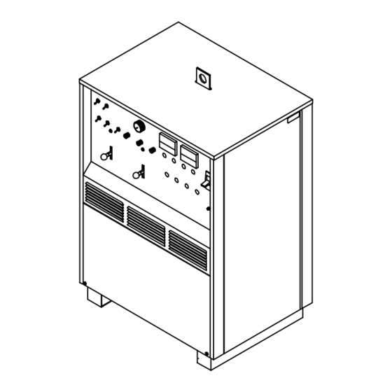
Page 15: Overall Dimensions And Base Mounting Hole Layout
2-6. Overall Dimensions And Base Mounting Hole Layout NOTE Overall dimensions (A, B, and C) include lifting eye, handles, hardware, etc. Inches Millimeters 1193 31-1/4 22-3/4 25-1/2 2-13/16 1-15/16 9/16 Dia 14 Dia 4 Holes 4 Holes Weight 887 lb (402 kg) ST-800 338 2-7. -
Page 16: Lower Front Panel
2-9. Lower Front Panel Work Output Terminal Electrode Output Terminal High Frequency Intensity Control (See Section 3-9) Spark Gaps (See Section 4-2) Circuit Breaker CB1 (See Section 2-11) Gas Valve Fittings 115 VAC Duplex Receptacle Remote Contactor And Cur- rent Control Receptacle Ref. -
Page 17: Volts Ac Duplex Receptacle And Circuit Breaker
2-11. 115 Volts AC Duplex Receptacle And Circuit Breaker 115 Volts AC Duplex Receptacle This welding power source sup- plies up to 15 amperes of 115 volts ac power. Receptacle is protected from over- load by circuit breaker CB1. Circuit Breaker CB1 CB1 protects the 115 volts ac wind- ing of transformer T1 from over- 115V 15 A... -
Page 18: Remote 14 Receptacle Information And Connections
2-13. Remote 14 Receptacle Information And Connections Remote 14 Receptacle RC2 (See Section 2-14) Keyway Plug Threaded Collar To connect to receptacle, align keyway, insert plug, and tighten threaded collar. sb7.1 5/94 – Ref. ST-144 405-B / Ref. S-0004-A / S-0750 2-14. -
Page 19: Positioning Jumper Links
2-15. Positioning Jumper Links Y Disconnect and lockout/tag- out input power before plac- ing or moving jumper links. Jumper links allow operation on dif- ferent input voltages and are facto- ry set for the highest input voltage. Check input voltage available at site. -
Page 20: Connecting Input Power
2-17. Connecting Input Power WARNING HIGH-FREQUENCY RADIATION can ELECTRIC SHOCK can kill. interfere with radio navigation, safety Do not touch live electrical parts. services, computers, and communica- Turn Off welding power source, and disconnect tions equipment. input power before inspecting or installing. Have only qualified person familiar with electronic Have only qualified persons install unit. -
Page 21: Section 3 - Operation
SECTION 3 – OPERATION WARNING ELECTRIC SHOCK can kill. ARC RAYS can burn eyes and skin; NOISE can damage hearing. Always wear dry insulating gloves. Wear welding helmet with correct shade of filter. Insulate yourself from work and ground. Wear correct eye, ear, and body protection. Do not touch live electrical parts. -
Page 22: Work Clamp
3-2. Work Clamp Work Clamp Connect work clamp to a clean, Tools Needed: paint-free location on workpiece, as close to weld area as possible. Use wire brush or sandpaper to clean metal at weld joint area. Use chipping hammer to remove slag after welding. -
Page 23: Start Amperage Controls
3-4. Amperage Controls Amperage Adjustment Control Use control to select weld output amperage. Amperage Control Switch Use switch to select way of control- ling amperage adjustment. For front panel control, place switch in the Panel position. For remote control, place switch in Remote 14 position (see Section 2-13). -
Page 24: Output (Contactor) Switch
3-6. Output (Contactor) Switch Output (Contactor) Switch Use switch to select way of control- ling unit output. For weld output, place switch in On position. For remote output control, place Weld output terminals are switch in Remote 14 position (see energized when switch is Section 2-13). -
Page 25: Postflow Time Control
3-8. Postflow Time Control Postflow Time Control Use control to set the length of time in seconds gas (and coolant if appli- cable) flows after welding stops. 3-9. High Frequency Controls WARNING USING HIGH FREQUENCY WITH THE SHIELDED METAL ARC WELDING (SMAW) PROCESS can result in serious personal injury. -
Page 26: Ammeter And Voltmeter
3-11. Ammeter And Voltmeter Ammeter Ammeter displays weld amperage output of unit. Voltmeter Voltmeter displays voltage at the weld output terminals, but not nec- essarily the welding arc due to cable resistance, poor connec- tions, etc. 3-12. Power Switch Power Switch Use this switch to turn unit and pilot light On and Off. -
Page 27: Shielding Gas
3-13. Shielding Gas Shielding Gas Cylinder Valve Fingertip Control Foot Control Open valve on cylinder just before welding. Fingertip control or foot control turns weld output and gas flow on and off. Close valve on cylinder when fin- ished welding. sb5.3* 5/94 –... -
Page 28: Section 4 - Maintenance & Troubleshooting
SECTION 4 – MAINTENANCE & TROUBLESHOOTING 4-1. Routine Maintenance 3 Months 3 Months Replace Replace Unreadable Cracked Labels Parts Section – – 14-Pin Cord Tape Or Replace Cracked Cables – – Gas Hose Torch Cable Clean 6 Months Tighten Weld 2-12 Blow Out Terminals... -
Page 29: Troubleshooting
4-3. Troubleshooting Trouble Remedy No weld output; unit completely inoperative. Place Power switch in On position (see Section 3-12). Place line disconnect switch in the On position (see Section 2-17). Check and replace line fuse(s) or reset circuit breakers (see Section 2-17). Check for proper input connections (see Section 2-17). -
Page 30: Section 5 - Electrical Diagram
SECTION 5 – ELECTRICAL DIAGRAM Figure 5-1. Circuit Diagram For Welding Power Source OM-350 Page 26... - Page 31 SD-202 703-A OM-350 Page 27...
-
Page 32: Section 6 - High Frequency
SECTION 6 – HIGH FREQUENCY 6-1. Welding Processes Requiring High Frequency High-Frequency Voltage TIG – helps arc jump air gap between torch and workpiece and/ or stabilize the arc. Work high_freq 12/96 – S-0693 6-2. Incorrect Installation Weld Zone 11, 12 50 ft (15 m) Sources of Direct High-Frequency... -
Page 33: Correct Installation
6-3. Correct Installation Weld Zone 50 ft (15 m) 50 ft (15 m) Ground all metal ob- jects and all wiring in welding zone using #12 AWG wire. Ground workpiece if required by codes. Nonmetal Building Metal Building Ref. S-0695 / Ref. S-0695 High-Frequency Source (welding Conduit Joint Bonding and Grounding Metal Building Requirements... -
Page 34: Or Ac Welding
SECTION 7 – SELECTING AND PREPARING TUNGSTEN ELECTRODE FOR DC OR AC WELDING ac/dc_gtaw 2/2000 Y Whenever possible and practical, use DC weld output instead of AC weld output. 7-1. Selecting Tungsten Electrode ( Wear Clean gloves To Prevent Contamination Of Tungsten Amperage Range - Gas Type - Polarity Electrode Diameter... -
Page 35: Preparing Tungsten Electrode For Welding
7-2. Preparing Tungsten Electrode For Welding Y Grinding the tungsten electrode produces dust and flying sparks which can cause injury and start fires. Use local exhaust (forced ventilation) at the grinder or wear an approved respirator. Read MSDS for safety infor- mation. -
Page 36: Section 8 - Guidelines For Tig Welding (Gtaw)
SECTION 8 – GUIDELINES FOR TIG WELDING (GTAW) 8-1. Positioning The Torch Y Weld current can damage electronic parts in vehicles. Disconnect both battery cables before welding on a vehicle. Place work clamp as close to the weld as possible. For additional information, see your distributor for a handbook on the Gas Tungsten Arc Weld-... -
Page 37: Torch Movement During Welding
8-2. Torch Movement During Welding Tungsten Without Filler Rod Welding direction Form pool Tilt torch Move torch to front of pool. Repeat process. Tungsten With Filler Rod Welding direction Form pool Tilt torch Add filler metal Remove rod Move torch to front of pool. -
Page 38: Positioning Torch Tungsten For Various Weld Joints
8-3. Positioning Torch Tungsten For Various Weld Joints Butt Weld And Stringer Bead “T” Joint 20-40 Lap Joint Corner Joint ST-162 003 / S-0792 OM-350 Page 34... - Page 39 Notes OM-350 Page 35...
-
Page 40: Section 9 - Parts List
SECTION 9 – PARTS LIST Hardware is common and not available unless listed. Fig 9-4 Fig 9-5 Fig 9-6 Fig 9-2 & 9-3 ST-127 627-C Figure 9-1. Main Assembly OM-350 Page 36... - Page 41 Replace Coils At Factory Or Factory Authorized Service Station/Service Distributor Item Dia. Part Description Quantity Mkgs. Figure 9-1. Main Assembly ....039 244 COVER, top .
- Page 42 Hardware is common and not available unless listed. ST-127 629-B Figure 9-2. Panel, Front (Lower Section) w/Components OM-350 Page 38...
- Page 43 Item Dia. Part Description Quantity Mkgs. Figure 9-2. Panel, Front (Lower Section) w/Components (Fig 9-1 Item 20) ....003 045 PANEL, front louvered .
- Page 44 Hardware is common and not available unless listed. Fig 9-7 24 22 Fig 9-11 ST-127 628-A Figure 9-3. Panel, Front (Upper Section) w/Components OM-350 Page 40...
- Page 45 Item Dia. Part Description Quantity Mkgs. Figure 9-3. Panel, Front (Upper Section) w/Components (Fig 9-1 Item 20) ..S5,7 ..059 081 SWITCH, polarity/selector (Fig 9-7) ....... .
- Page 46 Item Dia. Part Description Quantity Mkgs. Figure 9-4. Panel, Rear w/Components (Fig 9-1 Item 6) ....020 729 CHAMBER, plenum 18in ......... .
- Page 47 Item Dia. Part Description Quantity Mkgs. Figure 9-6. HF Panel (Fig 9-1 Item 19) 108 323 ....601 838 NUT, brs hex .375-16 jam hvy .
- Page 48 Item Dia. Part Description Quantity Mkgs. 059 081 Figure 9-7. Switch, Range/Polarity/Selector (Fig 9-3 Item 1) ....048 314 STUD, stl .250-20 x 9.500 .
- Page 49 Item Part Description Quantity Figure 9-8. Contact Board Assembly, Switch Selector AC/DC 059 084 (Fig 9-7 Item 2) ... . 070 318 CONTACT BOARD, movable switch (consisting of) ......
- Page 50 Item Part Description Quantity Figure 9-9. Contact Board Assembly, Switch Selector AC/DC 059 083 (Fig 9-7 Item 6) ... . 070 318 CONTACT BOARD, movable switch (consisting of) ......
- Page 51 Item Part Description Quantity Figure 9-10. Contact Board Assembly, Switch Polarity (Fig 9-7 Item 10) 059 082 ... . 070 317 CONTACT BOARD ASSEMBLY, movable switch (consisting of) ... . .
- Page 52 Item Dia. Part Description Quantity Mkgs. 119 939 Figure 9-11. Rectifier, SCR Main (Fig 9-3 Item 28) ....166 667 CLAMP, spring ..........
- Page 55 Call LIMITED WARRANTY – Subject to the terms and conditions APT, ZIPCUT & PLAZCUT Model Plasma Cutting below, Miller Electric Mfg. Co., Appleton, Wisconsin, warrants Torches 1-800-4-A-MILLER to its original retail purchaser that new Miller equipment sold...
-
Page 56: Options And Accessories
FAX: 44 (0) 1204-598066 www.MillerWelds.com Contact the Delivering Carrier for: File a claim for loss or damage during shipment. For assistance in filing or settling claims, contact your distributor and/or equipment manufacturer’s Transportation Department. PRINTED IN USA 2000 Miller Electric Mfg. Co. 6/00...
Need help?
Do you have a question about the Syncrowave 500 and is the answer not in the manual?
Questions and answers