
Related Manuals for Miller Electric Spectrum 875 Auto-Line


Summary of Contents for Miller Electric Spectrum 875 Auto-Line
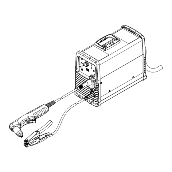
- Page 1 OM-242 880B 2010−05 Processes Air Plasma Cutting and Gouging Description Air Plasma Cutter Spectrum 875 Auto-Line And ICE-60T/TM Torch File: Plasma Cutters Visit our website at www.MillerWelds.com...
- Page 2 ISO 9001 Quality System Standard. particular model are also provided. Miller Electric manufactures a full line of welders and welding related equipment. For information on other quality Miller products, contact your local Miller distributor to receive the latest full line catalog or individual specification sheets.
-
Page 3: Table Of Contents
TABLE OF CONTENTS SECTION 1 − SAFETY PRECAUTIONS - READ BEFORE USING ........1-1. - Page 4 TABLE OF CONTENTS SECTION 6 − MECHANIZED OPERATION ............6-1.
-
Page 5: Section 1 − Safety Precautions - Read Before Using
SECTION 1 − SAFETY PRECAUTIONS - READ BEFORE USING pom_2010−03 Protect yourself and others from injury — read and follow these precautions. 1-1. Symbol Usage DANGER! − Indicates a hazardous situation which, if Indicates special instructions. not avoided, will result in death or serious injury. The possible hazards are shown in the adjoining symbols or explained in the text. -
Page 6: Electric Shock Can Kill
FUMES AND GASES can be hazardous ELECTRIC SHOCK can kill. SIGNIFICANT DC VOLTAGE exists in Cutting produces fumes and gases. Breathing inverter power sources AFTER the re- these fumes and gases can be hazardous to your health. moval of input power. Keep your head out of the fumes. -
Page 7: Additional Symbols For Installation, Operation, And Maintenance
1-3. Additional Symbols For Installation, Operation, And Maintenance HOT PARTS can burn. FALLING EQUIPMENT can injure. D Do not touch hot parts bare handed. D Use lifting eye to lift unit only, NOT running gear, gas cylinders, or any other accessories. D Allow cooling period before working on equipment. -
Page 8: California Proposition 65 Warnings
1-4. California Proposition 65 Warnings For Gasoline Engines: Welding or cutting equipment produces fumes or gases which contain chemicals known to the State of California to Engine exhaust contains chemicals known to the State of cause birth defects and, in some cases, cancer. (California California to cause cancer, birth defects, or other reproduc- Health &... -
Page 9: Section 2 − Consignes De Sécurité − Lire Avant Utilisation
SECTION 2 − CONSIGNES DE SÉCURITÉ − LIRE AVANT UTILISATION pom_2010−03fre Se protéger et protéger les autres contre le risque de blessure — lire et respecter ces consignes. 2-1. Signification des symboles DANGER! − Indique une situation dangereuse qui si on Indique des instructions spécifiques. - Page 10 D Assurez−vous que le fil de terre du cordon d’alimentation est cor- D Ayez recours à des protège−tympans ou à un serre−tête ignifuges rectement relié à la borne de terre dans la boîte de coupure ou que afin d’éviter que les étincelles n’entrent dans vos oreilles. la fiche du cordon est branchée à...
-
Page 11: Dangers Supplémentaires En Relation Avec L'installation, Le Fonctionnement Et La Maintenance
D Ne coupez pas dans un endroit près d’opérations de décapage, de LES BOUTEILLES peuvent exploser nettoyage ou de vaporisation. La chaleur et les rayons d’arc peu- si elles sont endommagées. vent réagir avec les vapeurs et former des gaz hautement toxiques et irritants. - Page 12 Les CHAMPS ÉLECTROMAGNÉTIQUES (CEM) CHARGES ÉLECTROSTATI- peuvent affecter les implants médicaux. QUES peuvent endommager les cir- cuits imprimés. D Les porteurs de stimulateurs cardiaques et autres implants médicaux doivent rester D Etablir la connexion avec la barrette de terre à distance. avant de manipuler des cartes ou des pièces.
-
Page 13: Proposition Californienne 65 Avertissements
2-4. Proposition californienne 65 Avertissements cancérogène ainsi que provoquant des malformations Les équipements de soudage et de coupage produisent des congénitales ou autres problèmes de procréation. Se laver les fumées et des gaz qui contiennent des produits chimiques mains après toute manipulation. dont l’État de Californie reconnaît qu’ils provoquent des mal- Pour les moteurs à... -
Page 14: Section 3 − Definitions
A complete Parts List is available at www.MillerWelds.com SECTION 3 − DEFINITIONS 3-1. Symbols And Definitions For Nameplate And Serial Number/Rating Label Plasma Arc Cutting Adjust Air/Gas Low Air Pressure Amperes (PAC) Pressure Light No − Do Not Do Volts Increase Temperature This... -
Page 15: Section 4 − Installation
A complete Parts List is available at www.MillerWelds.com SECTION 4 − INSTALLATION 4-1. Serial Number And Rating Label Location The serial number and rating information for this product is located on the bottom. Use rating label to determine input power requirements and/or rated output. -
Page 16: Duty Cycle And Overheating
A complete Parts List is available at www.MillerWelds.com General −− −− Operating Temperature 5 to 104 F (−15 to 40 C) −− −− IP Code − Degree of protection provided by enclosure IP23CS −− −− IP − International Protection 2 − No ingress of foreign objects −−... -
Page 17: Torch Dimensions
A complete Parts List is available at www.MillerWelds.com 4-4. Torch Dimensions 8-27/32 in. (225 mm) Hand-Held Torch 1-1/2 in (38 mm) 4 in. (100 mm) 2-5/16 in. (58 mm) 1-1/16 in. (27 mm) Machine Torch 15-9/32 in. (388 mm) 2-9/64 in. (54 mm) 1-1/16 in. -
Page 18: Connecting Work Clamp And Gas/Air Supply
A complete Parts List is available at www.MillerWelds.com 4-6. Connecting Work Clamp and Gas/Air Supply Work Clamp Workpiece Connect work clamp to portion of workpiece that does not fall away after being cut. Connect work clamp to a clean, paint-free location on workpiece, as close to cutting area as possible. -
Page 19: Connecting And Disconnecting Torch
A complete Parts List is available at www.MillerWelds.com 4-7. Connecting And Disconnecting Torch Turn off power source and disconnect input power. Torch Connector Quick Connect Collar Nipple Receptacle Securing Pin To connect torch: Push torch connector onto receptacle and quick connect until collar secures nipple. -
Page 20: Power Cable Management Strap
A complete Parts List is available at www.MillerWelds.com 4-9. Power Cable Management Strap Power Cable Management Strap Coil power cable and secure to unit using the power cable management strap. Ref. 805 275-A 4-10. Selecting a Location Lifting Handle Use handle to lift unit. Line Disconnect Device Do not move or operate Locate unit near correct input... -
Page 21: Electrical Service Guide
A complete Parts List is available at www.MillerWelds.com 4-11. Electrical Service Guide NOTICE − INCORRECT INPUT POWER can damage this welding power source. Phase to ground voltage shall not exceed +10% of rated input voltage. Actual input voltage should not be 10% less than minimum and/or 10% more than maximum input voltages listed in table. If actual input voltage is outside this range, output may not be be available. -
Page 22: Extension Cord Data
A complete Parts List is available at www.MillerWelds.com 4-12. Extension Cord Data When calculating max. cord length, remember to include conductor length from line disconnect device to input power receptacle. Input Power Fuse Size Or Input Voltage Phase Hertz Circuit Breaker Rating Conductor Size Max. -
Page 23: Connecting 1-Phase Input Power
A complete Parts List is available at www.MillerWelds.com 4-13. Connecting 1-Phase Input Power Installation must meet all National and Local Codes − have only quali- fied persons make this installation. Disconnect and lockout/tagout in- put power before connecting input conductors from unit. Always connect green or green/ yellow conductor... -
Page 24: Connecting 3-Phase Input Power
A complete Parts List is available at www.MillerWelds.com 4-14. Connecting 3-Phase Input Power Installation must meet all National and Local Codes − have only quali- fied persons make this installation. Disconnect and lockout/tagout in- put power before connecting input conductors from unit. Always connect green or green/ yellow conductor... -
Page 25: Wiring Optional 240 Volt Plug (119 172) For Connection To Miller Bobcat
A complete Parts List is available at www.MillerWelds.com 4-15. Wiring Optional 240 Volt Plug (119 172) For Connection To Miller Bobcat, Trailblazer Or Hobart Champion 10,000 Check input voltage available at the power supply. The Auto-LineE circuitry in this unit automatically adapts the power source to the 240 volts, single-phase, 50 or 60 Hz primary voltage from the power... -
Page 26: Connecting To Miller Welder/Generator With A Three-Phase Ac Power Plant
A complete Parts List is available at www.MillerWelds.com 4-16. Connecting To Miller Welder/Generator With A Three-Phase AC Power Plant Three-Phase Generator Power Stop engine. Power and weld outputs are live at the same time. Discon- Three-Phase Power Connection nect insulate unused cables. -
Page 27: Generator Settings For Plasma Cutter Operation
A complete Parts List is available at www.MillerWelds.com 4-17. Generator Settings For Plasma Cutter Operation Engine Control Switch must be set at Set generator Fine Adjustment Control to 10 “RUN” position − not “RUN/IDLE”. for maximum auxiliary power, if applicable. The peak kW at arc stretch of this plasma power source is 15.5 kW. -
Page 28: Section 5 − Operation
A complete Parts List is available at www.MillerWelds.com SECTION 5 − OPERATION 5-1. Controls Ref. 234 155-A Output Control Cut/Gouge Switch Use only clean, dry air with 90 to 120 psi Use control to set cutting output. Place switch in appropriate position for de- (621 to 827 kPa) pressure. -
Page 29: Trigger Safety Lock
A complete Parts List is available at www.MillerWelds.com 5-2. Trigger Safety Lock Trigger Trigger Locked Trigger Unlocked 801 397-A 5-3. Plasma Cutting System Practices The pilot arc starts immediately when trigger is pressed. GOUGE Always connect work clamp to a clean, DO NOT start pilot arc without cutting or Set switch to either cut or gouge paint-free location on workpiece, as close to... -
Page 30: Sequence Of Cutting Operation
A complete Parts List is available at www.MillerWelds.com 5-4. Sequence Of Cutting Operation GOUGE Connect work clamp to a clean, paint-free Unit automatically regulates pressure to 70 psi location on workpiece, as close to cutting (483 kPa) for cutting. area as possible. Connect work clamp to portion of workpiece that does not fall away after being cut. -
Page 31: Sequence Of Gouging Operation
A complete Parts List is available at www.MillerWelds.com 5-5. Sequence Of Gouging Operation GOUGE Unit automatically regulates pressure to 60 psi (413 kPa) for gouging. Connect work clamp to a clean, paint-free location on workpiece, as close to cutting area as possible. Connect work clamp to portion of workpiece that does not fall away after being cut. -
Page 32: Sequence Of Piercing Operation
A complete Parts List is available at www.MillerWelds.com 5-6. Sequence Of Piercing Operation The pilot arc starts immediately when trigger is pressed. Recommended maximum piercing capacity is 7/16 in (11 mm). GOUGE Unit automatically regulates pressure to 70 psi (483 kPa) for cutting. Connect work clamp to a clean, Hold torch at an angle to the workpiece. -
Page 33: Cutting Speed
A complete Parts List is available at www.MillerWelds.com 5-7. Cutting Speed Mild Steel Material Thickness Recommended Cut Speeds Arc Current Inches mm/min 2184 1041 12.7 15.9 19.1 22.2 Stainless Material Thickness Recommended Cut Speeds Arc Current Inches mm/min 1829 12.7 15.9 19.0 22.2... -
Page 34: Section 6 − Mechanized Operation
(RMT1) or hot [RMT2 (+24 volts dc)] depending on plug position at RMT1 or Okay To Move RMT2 receptacle on Control board PC1. NOTE: The Spectrum 875 Auto-Line with factory-installed machine torch is Green shipped from the factory with the plug connected to RMT1 (dry contacts). To power a relay or isolated input module with +24 volts DC on black lead (socket 2) and circuit common on green lead (socket 4), see Section 6-4 or 6-5. -
Page 35: Volts Dc Hot Contacts For Relay Operation
A complete Parts List is available at www.MillerWelds.com 6-4. +24 Volts DC Hot Contacts For Relay Operation Turn off power source and disconnect input power. Remove wrapper (see Section 7-4). Control board PC1 can supply +24 volts DC from receptacle RMT2 to operate a customer-supplied relay for the Okay To Move signal. -
Page 36: Volts Dc Hot Contacts For Isolated Input Module Operation
A complete Parts List is available at www.MillerWelds.com 6-5. +24 Volts DC Hot Contacts For Isolated Input Module Operation Turn off power source and disconnect input power. Remove wrapper (see Section 7-4). Control board PC1 can supply +24 volts DC from receptacle RMT2 to operate customer-supplied isolated input module for the Okay... -
Page 37: Dry Contacts Using An External Power Supply For Relay Operation
A complete Parts List is available at www.MillerWelds.com 6-6. Dry Contacts Using An External Power Supply For Relay Operation Turn off power source and disconnect input power. Remove wrapper (see Section 7-4). Control board PC1 can provide dry contacts from receptacle RMT1 to operate a customer-supplied relay using an external power supply for the Okay To Move signal. -
Page 38: Dry Contacts Using An External Power Supply For Isolated Input Module Operation
A complete Parts List is available at www.MillerWelds.com 6-7. Dry Contacts Using An External Power Supply For Isolated Input Module Operation Turn off power source and disconnect input power. Remove wrapper (see Section 7-4). Control board PC1 can provide dry contacts from receptacle RMT1 to operate customer-supplied... -
Page 39: Remote Voltage Sense Connection
A complete Parts List is available at www.MillerWelds.com 6-8. Remote Voltage Sense Connection Turn off power source and disconnect input power. Remove wrapper (see Section 7-4). Remote voltage sense is an arc voltage output signal for automatic torch height adjustment. Snap-in Blank Secondary Interconnect Board PC4... -
Page 40: Cut Charts
A complete Parts List is available at www.MillerWelds.com 6-10. Cut Charts 60 Amp Machine Torch Shielded Consumables The following cut charts are based on a distance of 1/16 in. (1.5 mm) between torch and workpiece for all cuts. ICE-60TM Torch Shield Sense Tab* Retaining Cap... - Page 41 A complete Parts List is available at www.MillerWelds.com 40 Amp Machine Torch Shielded Consumables The following cut charts are based on a distance of 1/16 in. (1.5 mm) between torch and workpiece for all cuts. ICE-60TM Torch Shield Sense Tab* Retaining Cap Electrode Swirl Ring...
- Page 42 A complete Parts List is available at www.MillerWelds.com 40 Amp Machine Torch Extended Consumables The following cut charts are based on a distance of 1/16 in. (1.5 mm) between torch tip and workpiece for all cuts. ICE-60TM Torch Deflector Retaining Cap Electrode Swirl Ring 212 736...
-
Page 43: Section 7 − Maintenance & Troubleshooting
A complete Parts List is available at www.MillerWelds.com SECTION 7 − MAINTENANCE & TROUBLESHOOTING 7-1. Routine Maintenance Maintain more often Disconnect power during severe conditions. before maintaining. n = Check Z = Change ~ = Clean l = Replace Reference * To be done by Factory Authorized Service Agent Each n Torch Tip, Electrode,... -
Page 44: Checking/Replacing Retaining Cup, Tip, And Electrode
A complete Parts List is available at www.MillerWelds.com 7-3. Checking/Replacing Retaining Cup, Tip, And Electrode Overtightening will strip threads. Do not overtighten electrode, tip, and retaining cup during assembly. Do not cross-thread parts causing stripping. Use care during torch assembly and parts replacement. Inspect shield cup, tip, and electrode for wear before cutting or whenever cutting speed has been significantly reduced. -
Page 45: Wrapper Removal/Installation
A complete Parts List is available at www.MillerWelds.com 7-4. Wrapper Removal/Installation Turn power, disconnect input power plug from receptacle or turn off and lockout/tagout line dis- connect device before working on unit. Significant DC voltage can remain on capacitors after unit is Off. -
Page 46: Checking Or Replacing Filter Element (Part No. 227 877)
A complete Parts List is available at www.MillerWelds.com 7-5. Checking Or Replacing Filter Element (Part No. 227 877) Turn power, disconnect input power plug from receptacle or turn off and lockout/tagout line dis- connect device before working on unit. Significant DC voltage can remain on capacitors after unit is Off. -
Page 47: Status/Trouble Lights
A complete Parts List is available at www.MillerWelds.com 7-6. Status/Trouble Lights Light Condition Status/Possible Cause Power Input power is okay. When Power light is on, system is normal if these lights Pressure/Cup/T emp are off. Flashing rate is steady for 15 seconds or until torch trigger Input power was above 300 volts AC or below 156 volts Power is pressed again, whichever comes first. -
Page 48: Troubleshooting Power Source
A complete Parts List is available at www.MillerWelds.com 7-7. Troubleshooting Power Source Trouble Remedy Clean or replace worn consumables as necessary (see Section 7-3). No pilot arc; difficulty in establishing an arc. Check for damaged torch or torch cable. Check position of cut/gouge switch. If using cutting consumables, be sure that switch is in the CUT position. - Page 49 A complete Parts List is available at www.MillerWelds.com Trouble Remedy Arc goes out while cutting. Be sure work clamp is securely attached to a clean, paint-free, rust-free workpiece. Make sure drag shield is on the workpiece or the extended tip is 1/16 in. (1.6 mm) to 1/8 in. (3.2 mm) from workpiece while cutting (see Section 5-4).
-
Page 50: Troubleshooting Torch
A complete Parts List is available at www.MillerWelds.com 7-8. Troubleshooting Torch Trouble Remedy Torch travel speed too slow; increase travel speed (see Section 5-4). Arc goes on and off while cutting. Clean or replace worn consumables as necessary (see Section 7-3). Be sure work clamp is securely attached to a clean, paint-free, rust-free workpiece. - Page 51 Notes OM-242 880 Page 47...
-
Page 52: Section 8 − Electrical Diagram
SECTION 8 − ELECTRICAL DIAGRAM Figure 8-1. Circuit Diagram OM-242 880 Page 48... - Page 53 243 018-C OM-242 880 Page 49...
-
Page 54: Section 9 − Parts List
SECTION 9 − PARTS LIST A complete Parts List is available on-line at www.MillerWelds.com 9-1. Recommended Spare Parts Item Dia. Part Mkgs. Description Quantity Recommended Spare Parts ....234843 Label, Ice 60t Consumables . - Page 55 Item Part Item Part Description Description 215 594 Handle W/Screws (1) 215 606 Clip, Retaining (1) 215 478 Kit, Cup Sensor (1) 212 735 O-Ring, Main Body (1) 215 479 Torch Head Repair Kit (1) 234 829 Kit, Ice 60T/TM Quick Connect W/Wing Head Fastener (1) 185 833 Switch Assy w/Spring (1)
- Page 56 See Figure 8-1 for Item Part additional consumable parts. Description 215 607 Sleeve, Torch Position (1) 234 172 Torch Lead, Replacement W/QD 25 ft (1) 234 173 Torch Lead, Replacement W/QD 50 ft (1) 215 599 Torch Sleeve (1) 215 598 Main Body W/Switch (1) 195 513 Remote Pendant Control (1)
- Page 57 Notes...
- Page 58 Notes...
- Page 59 LIMITED WARRANTY − Subject to the terms and conditions 90 Days — Parts Call below, Miller Electric Mfg. Co., Appleton, Wisconsin, warrants to its Accessory (Kits) 1-800-4-A-MILLER original retail purchaser that new Miller equipment sold after the...
- Page 60 Contact the Delivering Carrier to: File a claim for loss or damage during shipment. For assistance in filing or settling claims, contact your distributor and/or equipment manufacturer’s Transportation Department. ORIGINAL INSTRUCTIONS − PRINTED IN USA 2010 Miller Electric Mfg. Co. 2010−01...
Need help?
Do you have a question about the Spectrum 875 Auto-Line and is the answer not in the manual?
Questions and answers
Miller plazma 875 sikakliq ışığının yanması sonrunu
The indicator lights on the Miller Electric Spectrum 875 Auto-Line plasma cutter provide status information:
- Power light flashing at two quick cycles with a one-second pause: Input power is above 300V AC or below 156V AC. A qualified technician should check the input power.
- Pre-charge PTCs overheated: Allow 15 minutes for the unit to cool.
- Pressure status light flashing at two quick flashes with a one-second pause for 15 seconds: Unit-regulated pressure is too high. Check input pressure (90-120 PSI). If the issue persists, a Factory Authorized Service Agent should inspect the unit. Reset the power switch.
- Pressure status light flashing steadily for 15 seconds or until the torch trigger is pressed: Regulated pressure is too low. Check for leaks in the torch and ensure input pressure is between 90-120 PSI during cutting.
These lights help diagnose power and pressure issues in the plasma cutter.
This answer is automatically generated
@Mr. Anderson Cihazı ise salarken sıcaklık ışığı yanıyor ve sönmüyor bu sorunda Cihazın işlemesini engelliyor. Soru şuki Cihazı işe salarken neden temp (sıcaklık ışığı) yanıyor ve bu sorunun çaresi ne? Bununla bağlı yardımcı ola bilen varmi??