
Related Manuals for Miller Soft Start 2-2F


Summary of Contents for Miller Soft Start 2-2F
-
Page 1: Soft Start
OM-189 112 January 1998 Eff. w/Serial Number ME144734 Processes TIG (GTAW) Welding Stick (SMAW) Welding Description Soft Start 2-2F Visit our website at www.MillerWelds.com... - Page 2 Warranty and service information for your particular model are also provided. Miller Electric manufactures a full line of welders and welding related equipment. For information on other quality Miller...
-
Page 3: Table Of Contents
TABLE OF CONTENTS SECTION 1 – SAFETY PRECAUTIONS - READ BEFORE USING ..1-1. Symbol Usage ..........1-2. -
Page 4: Declaration Of Conformity
Declaration of Conformity “CE” Dichiarazione di Conformità Manufactruer’s Name: MILLER Europe S.p.A. Nome del Costruttore: Manufacturer’s Address: Via Privata Iseo, 6/E Indirizzo Costruttore: 20098 San Giuliano Milanese, Italy Declares that this product: Soft Start 1, 2 and 2F Dichiara che il Prodotto: Conforms to the following Directives and Standards: È... -
Page 5: Section 1 - Safety Precautions - Read Before Using
SECTION 1 – SAFETY PRECAUTIONS - READ BEFORE USING som _nd_4/98 1-1. Symbol Usage Means Warning! Watch Out! There are possible hazards with this procedure! The possible hazards are shown in the adjoining symbols. This group of symbols means Warning! Watch Out! possible Y Marks a special safety message. - Page 6 ARC RAYS can burn eyes and skin. BUILDUP OF GAS can injure or kill. D Shut off shielding gas supply when not in use. Arc rays from the welding process produce intense D Always ventilate confined spaces or use visible and invisible (ultraviolet and infrared) rays that can burn eyes and skin.
-
Page 7: Additional Symbols For Installation, Operation, And Maintenance
1-3. Additional Symbols For Installation, Operation, And Maintenance FIRE OR EXPLOSION hazard. MOVING PARTS can cause injury. D Do not install or place unit on, over, or near D Keep away from moving parts such as fans. combustible surfaces. D Keep all doors, panels, covers, and guards D Do not install unit near flammables. -
Page 8: Emf Information
1-5. EMF Information Considerations About Welding And The Effects Of Low Frequency 1. Keep cables close together by twisting or taping them. Electric And Magnetic Fields 2. Arrange cables to one side and away from the operator. Welding current, as it flows through welding cables, will cause electro- magnetic fields. -
Page 9: Section 2 - Definitions
SECTION 2 – DEFINITIONS 2-1. Symbols and Definitions Note Some symbols are found only on CE products. Amperage Control/ Gas Tungsten Arc Shielded Metal Arc Amperes Panel Welding (GTAW) Welding (SMAW) Do Not Switch Temperature Arc Force (DIG) Percent While Welding Output Circuit Breaker Remote... -
Page 10: Duty Cycle And Overheating
3-2. Duty Cycle and Overheating Duty Cycle is percentage of 10 min- Model 2F utes that unit can weld at rated load without overheating. If unit overheats, thermostat(s) opens, output stops, and cooling fan runs. Wait fifteen minutes for unit to cool. Reduce amperage or duty cycle before welding. -
Page 11: Installing Mounting Brackets (Optional)
3-4. Installing Mounting Brackets (Optional) NOTE The supplied mounting brackets allow the high-frequency unit to be mounted under a Maxstar welding power source. If connecting to the Maxstar for input power, make input power connections according to Section 3-9B before installing mounting brackets. Maxstar Welding Power Source Position on top of high-frequency... -
Page 12: Installing Gas Supply
3-5. Installing Gas Supply Obtain gas cylinder and chain to running gear, wall, or other station- ary support so cylinder cannot fall and break off valve. Cylinder Valve Remove cap, stand to side of valve, and open valve slightly. Gas flow blows dust and dirt from valve. -
Page 13: Remote 14 Receptacle Information And Connections
3-6. Remote 14 Receptacle Information and Connections Remote 14 Receptacle RC Keyway Plug Threaded Collar To connect to receptacle, align keyway, insert plug, and tighten threaded collar. C L N sb7.1 5/94 – ST-800 293 / Ref. S-0004-A / S-0750 Socket* Socket Information 24 volts ac. -
Page 14: Connecting To Weld Input And Output Receptacles
3-8. Connecting to Weld Input and Output Receptacles Negative (–) Input Plug Connect negative (–) input plug to negative (–) weld output receptacle on welding power source. Positive (+) Input Plug (Red Input Receptacle Connections Mark) Connect positive (+) input plug to positive (+) weld output receptacle on welding power source. -
Page 15: Connecting Input Power
3-9. Connecting Input Power A. 115 or 230 VAC Input Power Cord Connections GND/PE NOTE Be sure that the Soft Start is a 230 VAC model. Internal connections cannot be made to a Maxstar 175 for input power. OM-189 112 Page 11... - Page 16 B. Power Connections to a Maxstar 91 or 152 Welding Power Source NOTE Be sure that the Soft Start is a 230 VAC model. Welding Power Source Internal connections cannot be made to a Remove wrapper. Maxstar 175 for input power. Snap-In Blank Remove blank and install supplied Parts needed for this procedure are...
-
Page 17: Section 4 - Operation
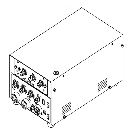
SECTION 4 – OPERATION 4-1. Controls Power ON Switch Process Selector Switch GTAW welding (DC) with high frequency arc starting GTAW welding (DC) with lift arc starting SMAW Amperage Control Panel or Remote Trigger Operation Switch Impulse - torch trigger is closed, arc starts, the trigger released and the weld prog- resses. -
Page 18: Work Clamp
4-3. Work Clamp Work Clamp Tools Needed: Connect work clamp to a clean, paint-free location on workpiece, as close to weld area as possible. Use wire brush or sandpaper to clean metal at weld joint area. Use chipping hammer to remove slag after welding. -
Page 19: Section 5 - Maintenance & Troubleshooting
SECTION 5 – MAINTENANCE & TROUBLESHOOTING 5-1. Troubleshooting Problem Probable Cause Remedy Lack of HF, difficult arc starting. Leakage of HF through TIG torch cables. Prevent torch cables from contacting work circuit. Starting current unstable. Torch or work cables broken or damaged. Repair or replace damaged parts. -
Page 20: Section 6 - Electrical Diagrams
SECTION 6 – ELECTRICAL DIAGRAMS OM -189 112 Page 16... -
Page 21: Section 7 - Parts List
SECTION 7 – PARTS LIST 7-1. Main Assembly for Soft Start 1, 2, and 2F Qty. Qty. Qty. Qty. Qty. Qty. Item Ref. Code mod 1 mod 2 mod 2F Item Ref. Code mod 1 mod 2 mod 2F 656089022 OM.0.0.17 Cable (+) 027112017 OM.0.2 027024078 OP.0.1... - Page 22 7-2. Control Panel for Soft Start 1, 2, and 2F 1 1 1 1 2-12 2-11 2-13 Qty. Qty. Qty. Qty. Qty. Qty. Item Ref. Code mod 1 mod 2 mod 2F Item Ref. Code mod 1 mod 2 mod 2F 316029604 PM.0.0.2 (50mmq) 056076152 DD.0.0.7...
- Page 23 LIMITED WARRANTY – Subject to the terms and conditions APT, ZIPCUT & PLAZCUT Model Plasma Cutting below, Miller Electric Mfg. Co., Appleton, Wisconsin, Torches warrants to its original retail purchaser that new Miller Remote Controls...
- Page 24 International Headquarters–USA Phone: 414-735-4505 USA & Canada FAX: 920-735-4134 International FAX: 920-735-4125 European Headquarters – United Kingdom Phone: 44 (0) 1204-593493 FAX: 44 (0) 1204-598066 Miller Europe Italy Phone: 39 (0) 2982901 PRINTED IN USA 1999 Miller Electric Mfg. Co. 7/99...