
Related Manuals for Miller Electric Millermatic 212


Summary of Contents for Miller Electric Millermatic 212
- Page 1 OM-232 384C 2008−01 Processes MIG (GMAW) Welding Flux Cored (FCAW) Welding Description Arc Welding Power Source and Wire Feeder Millermatic 212 File: MIG (GMAW) Visit our website at www.MillerWelds.com...
- Page 2 ISO 9001:2000 Quality System Standard. particular model are also provided. Miller Electric manufactures a full line of welders and welding related equipment. For information on other quality Miller products, contact your local Miller distributor to receive the latest full line catalog or individual specification sheets.
-
Page 3: Table Of Contents
TABLE OF CONTENTS SECTION 1 − SAFETY PRECAUTIONS - READ BEFORE USING ....... . . 1-1. - Page 4 TABLE OF CONTENTS SECTION 8 − MIG WELDING (GMAW) GUIDELINES ..........8-1.
-
Page 5: Section 1 − Safety Precautions - Read Before Using
SECTION 1 − SAFETY PRECAUTIONS - READ BEFORE USING som _2007−04 Protect yourself and others from injury — read and follow these precautions. 1-1. Symbol Usage DANGER! − Indicates a hazardous situation which, if Indicates special instructions. not avoided, will result in death or serious injury. The possible hazards are shown in the adjoining symbols or explained in the text. - Page 6 D Do not use welder to thaw frozen pipes. FUMES AND GASES can be hazardous. D Remove stick electrode from holder or cut off welding wire at contact tip when not in use. Welding produces fumes and gases. Breathing D Wear oil-free protective garments such as leather gloves, heavy these fumes and gases can be hazardous to your shirt, cuffless trousers, high shoes, and a cap.
-
Page 7: Additional Symbols For Installation, Operation, And Maintenance
1-3. Additional Symbols For Installation, Operation, And Maintenance FIRE OR EXPLOSION hazard. MOVING PARTS can cause injury. D Do not install or place unit on, over, or near D Keep away from moving parts such as fans. combustible surfaces. D Keep all doors, panels, covers, and guards D Do not install unit near flammables. -
Page 8: California Proposition 65 Warnings
1-4. California Proposition 65 Warnings For Gasoline Engines: Welding or cutting equipment produces fumes or gases which contain chemicals known to the State of California to Engine exhaust contains chemicals known to the State of cause birth defects and, in some cases, cancer. (California California to cause cancer, birth defects, or other reproduc- Health &... -
Page 9: Section 2 − Consignes De Sécurité − Lire Avant Utilisation
SECTION 2 − CONSIGNES DE SÉCURITÉ − LIRE AVANT UTILISATION fre_som_2007−04 Se protéger et protéger les autres contre le risque de blessure — lire et respecter ces consignes. 2-1. Symboles utilisés DANGER! − Indique une situation dangereuse qui si on Indique des instructions spécifiques. - Page 10 Il reste une TENSION DC NON NÉGLIGEABLE dans LE SOUDAGE peut provoquer un in- les sources de soudage onduleur quand on a cendie ou une explosion. coupé l’alimentation. Le soudage effectué sur des conteneurs fermés tels D Arrêter les convertisseurs, débrancher le courant électrique et que des réservoirs, tambours ou des conduites peu décharger les condensateurs d’alimentation selon les instructions provoquer leur éclatement.
-
Page 11: Dangers Supplémentaires En Relation Avec L'installation, Le Fonctionnement Et La Maintenance
D Protéger les bouteilles de gaz comprimé d’une chaleur excessive, ACCUMULATIONS des chocs mécaniques, des dommages physiques, du laitier, des risquent de provoquer des blessures flammes ouvertes, des étincelles et des arcs. ou même la mort. D Placer les bouteilles debout en les fixant dans un support station- D Fermer l’alimentation du gaz protecteur en cas naire ou dans un porte-bouteilles pour les empêcher de tomber ou de non-utilisation. -
Page 12: Proposition Californienne 65 Avertissements
LES FILS DE SOUDAGE peuvent LE RAYONNEMENT HAUTE FRÉ- provoquer des blessures. QUENCE (H.F.) risque de provoquer des interférences. D Ne pas appuyer sur la gâchette avant d’en avoir reçu l’instruction. D Le rayonnement haute fréquence (H.F.) peut D Ne pas diriger le pistolet vers soi, d’autres per- provoquer des interférences avec les équipe- sonnes ou toute pièce mécanique en enga- ments de radio−navigation et de communica-... -
Page 13: Principales Normes De Sécurité
2-5. Principales normes de sécurité Safety in Welding, Cutting, and Allied Processes, ANSI Standard Z49.1, L4W 5NS (téléphone : 800-463-6727 ou à Toronto 416-747-4044, site de Global Engineering Documents (téléphone : 1-877-413-5184, site Internet : www.csa-international.org). Internet : www.global.ihs.com). Safe Practice For Occupational And Educational Eye And Face Protec- tion, ANSI Standard Z87.1, de American National Standards Institute, Recommended Safe Practices for the Preparation for Welding and Cut- 11 West 43rd Street, New York, NY 10036-8002 (téléphone :... - Page 14 OM-232 384 Page 10...
-
Page 15: Section 3 − Definitions
A complete Parts List is available at www.MillerWelds.com SECTION 3 − DEFINITIONS 3-1. Symbols And Definitions Do Not Switch Wire Feed Output Duty Cycle While Welding Volts Increase Gas Metal Arc Wire Feed Spool Welding (GMAW) Gas Input Gas Output Rated No-Load Voltage Input Press To Reset... -
Page 16: Welding Power Source Duty Cycle And Overheating
A complete Parts List is available at www.MillerWelds.com 4-2. Welding Power Source Duty Cycle And Overheating Duty Cycle is percentage of 10 min- utes that unit can weld at rated load without overheating. If unit overheats, thermostat(s) opens, output stops, and cooling fan runs. -
Page 17: Connecting To Weld Output Terminals
A complete Parts List is available at www.MillerWelds.com 4-4. Connecting To Weld Output Terminals Do not place anything between weld cable terminal and copper bar. Tools Needed: 3/4 in (19 mm) 803 778-A Correct Installation Incorrect Installation Weld Output Terminal output terminal and secure with nut so that Turn off power before connecting to weld cable terminal is tight against copper... -
Page 18: Connecting An Optional Spool Gun
A complete Parts List is available at www.MillerWelds.com 4-6. Connecting An Optional Spool Gun Barbed Fitting If spool gun gas hose is equipped with a pre-installed barbed fitting, cut off fitting from end of hose. Connect spool gun gas hose to barbed fitting. -
Page 19: Installing Gas Supply
A complete Parts List is available at www.MillerWelds.com 4-8. Installing Gas Supply Obtain gas cylinders and chain to running gear, wall, or other stationary support so cylinders cannot fall and break off valve. Cylinder Valve Remove cap, stand to side of valve, and open valve slightly. -
Page 20: Installing Mig Wire Spool And Adjusting Hub Tension
A complete Parts List is available at www.MillerWelds.com 4-9. Installing MIG Wire Spool and Adjusting Hub Tension Use compression spring When a slight force is needed with 8 in (200 mm) spools. to turn spool, tension is set. To install either a 1 lb or 2 lb wire Installing 1 Or 2 lb Wire Spool spool, follow the procedure as Spindle... -
Page 21: Positioning Jumper Links
A complete Parts List is available at www.MillerWelds.com 4-10. Positioning Jumper Links Check input voltage available at Tools Needed: site. Jumper Links Access Door 3/8 in Open door. Jumper Link Label Check label − only one is on unit. 200 VOLTS 230 VOLTS Input Voltage Jumper Links Move jumper links to match input... -
Page 22: Selecting A Location And Connecting Input Power
A complete Parts List is available at www.MillerWelds.com 4-12. Selecting A Location And Connecting Input Power 18 in (457 mm) of Do not move or operate unit space for airflow where it could tip. =GND/PE Earth Ground 230 VAC, 1 804 924-A Plug (NEMA Type 6-50P) Disconnect Device Line Terminals... -
Page 23: Threading Welding Wire
A complete Parts List is available at www.MillerWelds.com 4-13. Threading Welding Wire Wire Spool Welding Wire Inlet Wire Guide Pressure Adjustment Knob Drive Roll Outlet Wire Guide Gun Conduit Cable Lay gun cable out straight. Tools Needed: Hold wire tightly to keep it from unraveling. -
Page 24: Section 5 − Operation
A complete Parts List is available at www.MillerWelds.com SECTION 5 − OPERATION 5-1. Controls Ref. 226 648-C Voltage Control Wire Speed Control Over Temp Light Set Wire Speed control according to the Set Voltage control according to the If unit overheats, light turns on and output parameter chart. - Page 25 A complete Parts List is available at www.MillerWelds.com Notes OM-232 384 Page 21...
-
Page 26: Weld Parameter Chart
A complete Parts List is available at www.MillerWelds.com 5-2. Weld Parameter Chart Suggested Suggested Wire Sizes Shielding Gases Wire Types (Diameters) And Flow Rate Material STEEL Solid (or hard) 75% Ar/ 0.023" (0.6mm) 25 % CO ER70s−6 25 cfh (Ar/CO 0.030"... - Page 27 A complete Parts List is available at www.MillerWelds.com Select Voltage and Wire 3/8" 1/4" 3/16" 1/8" 14 ga. 18 ga. 22 ga. Speed Based on Thickness of Metal Being Welded. (9.5 mm) (6.4 mm) (4.8 mm) (3.2 mm) (2.0 mm) (1.2 mm) (0.8 mm) 5/90...
-
Page 28: Section 6 − Maintenance &Troubleshooting
A complete Parts List is available at www.MillerWelds.com SECTION 6 − MAINTENANCE &TROUBLESHOOTING 6-1. Routine Maintenance Disconnect power Maintain more often before maintaining. during severe conditions. n = Check Z = Change ~ = Clean l = Replace Reference * To be done by Factory Authorized Service Agent Every Months l Unreadable Labels... -
Page 29: Aligning Drive Rolls And Wire Guide
A complete Parts List is available at www.MillerWelds.com 6-4. Aligning Drive Rolls and Wire Guide Turn Off power. View is from top of drive rolls look- ing down with pressure assembly open. Drive Roll Securing Nut Correct Incorrect Drive Roll Wire Guide Welding Wire Drive Gear... - Page 30 A complete Parts List is available at www.MillerWelds.com Wire Drive/Gun Trouble Remedy Straighten gun cable and/or replace damaged parts (see welding gun Owner’s Manual). Electrode wire feeding stops during welding. welding. Adjust drive roll pressure (see Section 4-13). Readjust hub tension (see Section 4-9). Replace contact tip if blocked (see welding gun Owner’s Manual).
-
Page 31: Section 7 − Electrical Diagram
SECTION 7 − ELECTRICAL DIAGRAM 229 597-B Figure 7-1. Welding Power Source Circuit Diagram OM-232 384 Page 27... -
Page 32: Section 8 − Mig Welding (Gmaw) Guidelines
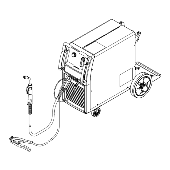
SECTION 8 − MIG WELDING (GMAW) GUIDELINES 8-1. Typical MIG Process Connections Weld current can damage electronic parts in vehicles. Disconnect both battery cables before welding on a vehicle. Place work clamp as close to the weld as possible. Regulator/ Flowmeter Wire Feeder/ Power Source... -
Page 33: Typical Mig Process Control Settings
8-2. Typical MIG Process Control Settings These settings are guidelines only. Material and wire type, joint design, fitup, position, shielding gas, etc. affect settings. Test welds to be sure they comply to specifications. Material thickness determines weld parameters. 1/8 or 0.125 in Convert Material Thickness to Amperage (A) -
Page 34: Holding And Positioning Welding Gun
8-3. Holding And Positioning Welding Gun Welding wire is energized when gun trigger is pressed. Before lowering helmet and pressing trigger, be sure wire is no more than 1/2 in (13 mm) past end of nozzle, and tip of wire is positioned correctly on seam. Hold Gun and Control Gun Trigger Workpiece... -
Page 35: Conditions That Affect Weld Bead Shape
8-4. Conditions That Affect Weld Bead Shape Weld bead shape depends on gun angle, direction of travel, electrode extension (stickout), travel speed, thickness of base metal, wire feed speed (weld current), and voltage. Push Drag Perpendicular GUN ANGLES AND WELD BEAD PROFILES Short Normal Long... -
Page 36: Gun Movement During Welding
8-5. Gun Movement During Welding Normally, a single stringer bead is satisfactory for most narrow groove weld joints; however, for wide groove weld joints or bridging across gaps, a weave bead or multiple stringer beads works better. Stringer Bead − Steady Movement Along Seam Weave Bead −... -
Page 37: Troubleshooting − Excessive Spatter
8-8. Troubleshooting − Excessive Spatter Excessive Spatter − scattering of molten metal particles that cool to solid form near weld bead. S-0636 Possible Causes Corrective Actions Wire feed speed too high. Select lower wire feed speed. Voltage too high. Select lower voltage range. Electrode extension (stickout) too long. -
Page 38: Troubleshooting − Lack Of Penetration
8-11. Troubleshooting − Lack Of Penetration Lack Of Penetration − shallow fusion between weld metal and base metal. Lack of Penetration Good Penetration S-0638 Possible Causes Corrective Actions Improper joint preparation. Material too thick. Joint preparation and design must provide access to bottom of groove while maintaining proper welding wire extension and arc characteristics. -
Page 39: Troubleshooting − Waviness Of Bead
8-14. Troubleshooting − Waviness Of Bead Waviness Of Bead − weld metal that is not parallel and does not cover joint formed by base metal. S-0641 Possible Causes Corrective Actions Welding wire extends too far out of nozzle. Be sure welding wire extends not more than 1/2 in (13 mm) beyond nozzle. Unsteady hand. -
Page 40: Common Mig Shielding Gases
8-16. Common MIG Shielding Gases This is a general chart for common gases and where they are used. Many different combinations (mixtures) of shielding gases have been developed over the years. The most commonly used shielding gases are listed in the following table. - Page 41 Problem Probable Cause Remedy Welding arc not stable. Wire slipping in drive rolls. Adjust pressure setting on wire feed rolls. Replace worn drive rolls if necessary. Wrong size gun liner or contact tip. Match liner and contact tip to wire size and type. Incorrect voltage setting for selected wire feed speed on Readjust welding parameters.
-
Page 42: Section 9 − Parts List
SECTION 9 − PARTS LIST 9-1. Drive Roll And Wire Guide Kits Base selection of drive rolls upon the following recommended usages: V-Grooved rolls for hard wire. U-Grooved rolls for soft and soft shelled cored wires. U-Cogged rolls for extremely soft shelled wires (usually hard surfacing types). V-Knurled rolls for hard shelled cored wires. - Page 43 LIMITED WARRANTY − Subject to the terms and conditions Induction Heating Coils and Blankets, Cables, and Call below, Miller Electric Mfg. Co., Appleton, Wisconsin, warrants to Non-Electronic Controls 1-800-4-A-MILLER its original retail purchaser that new Miller equipment sold after APT &...
- Page 44 1-800-4-A-Miller www.MillerWelds.com Contact the Delivering Carrier to: File a claim for loss or damage during shipment. For assistance in filing or settling claims, contact your distributor and/or equipment manufacturer’s Transportation Department. PRINTED IN USA 2008 Miller Electric Mfg. Co. 2008−01...
Need help?
Do you have a question about the Millermatic 212 and is the answer not in the manual?
Questions and answers