Lifebreath 200ERV Operation And Installation Manual
Energy recovery ventilator, controlair 15 & analog controls
Hide thumbs
Also See for 200ERV:
- Operation and installation manual (32 pages) ,
- Operation and installation manual (36 pages) ,
- Operation and installation manual (32 pages)
Table of Contents
Advertisement
Quick Links
C L E A N • F R E S H • A I R
OPERATION AND
INSTALLATION MANUAL
ControlAir 15
For Models:
200ERV
200ERVD
500ERV
700ERV
1200ERV
TO BE COMPLETED BY CONTRACTOR AFTER INSTALLATION
Installation Date
Contains
ControlAir 15
ControlAir 15
ControlAir 15
Analog Controls
Analog Controls
Installing Contractor
Telephone / Contact
Serial Number
IMPORTANT - PLEASE READ THIS
MANUAL BEFORE INSTALLING UNIT
CAUTION
Before installation, careful consideration must be
given to how the system will operate if connected to
any other piece of mechanical equipment, i.e. a forced
air furnace or air handler, operating at a higher static.
After installation, the compatibility of the two pieces of
equipment must be confirmed, by measuring the
airflow's of the Energy Recovery Ventilator (ERV), by
using the balancing procedure in this manual
It is always important to assess how the operation of
any Energy Recovery Ventilator may interact with
vented combustion equipment (ie. Gas Furnaces, Oil
Furnaces, Wood Stoves, etc.)
NEVER install an Energy Recovery Ventilator in a situ-
ation where its normal operation, lack of operation or
partial failure may result in the backdrafting or improper
functioning of vented combustion equipment!!!
Model
* LEAVE FOR HOMEOWNER
NOTE: Due to ongoing research and product development, specifications,
ratings and dimensions are subject to change without notice.
®
TI-83C-NE
0007
Advertisement
Table of Contents

Related Manuals for Lifebreath 200ERV


Summary of Contents for Lifebreath 200ERV
- Page 1 INSTALLATION MANUAL Contains ControlAir 15 For Models: IMPORTANT - PLEASE READ THIS MANUAL BEFORE INSTALLING UNIT 200ERV ControlAir 15 CAUTION Before installation, careful consideration must be 200ERVD given to how the system will operate if connected to any other piece of mechanical equipment, i.e. a forced ControlAir 15 air furnace or air handler, operating at a higher static.
-
Page 2: Table Of Contents
Optional Remote Controls ............14 All LIFEBREATH Energy Recovery Ventilators carry a five year warranty on the Energy Recovery Part 2: Installation Core, Model 200ERV has a 5 year warranty on Installation ................16 replacement parts and Model 500, 700, and 1200 • Location ERV has a 2 year warranty on replacement parts. -
Page 3: Erv Questions And Answers
ERV Questions & Answers What is the difference between an HRV damp situation. In fact, about 2/3 of the energy used by and an ERV? the air conditioner system is to remove moisture. The core in an HRV (Heat Recovery Ventilator) trans- Therefore, when ventilating in the summer, less mois- fers heat from one air stream to the other. - Page 4 ® C L E A N • F R E S H • A I R Select the correct Lifebreath to match your climate Severe Conditions Moderate Conditions HRV recommended HRV recommended Double core high efficiency HRV recommended for extreme conditions...
-
Page 5: Select The Correct Size Erv
Selecting the Correct Size ERV Commercial and Institutional Requirements For outdoor air requirements, ASHRAE has produced the Ventilation Standard 62-1989 that is used to determine acceptable ventilation rates. This standard is referenced directly or used as “Good Engineering Practice” in most Code documents or design criteria. Small restaurants, Donut Shops and Fast food stores Bank Seats... -
Page 6: Model 200Erv
99-186 Weatherhoods, Two - 6” (150mm) does not drop below 25°F (-4°C) c/w 1/4” (6mm) mesh screen __________________________ DATE: 511 McCormick Blvd. London, ON N5W 4C8 Phone: (519) 457-1904 ___________________________________ PROJECT: Fax: (519) 457-1676 Email: nutech@lifebreath.com __________________________ MECHANICAL CONTRACTOR: TI-98E 0006... -
Page 7: 200Ervd
It is not recommended for regions where the temperature does not drop below 25°F (-4°C) c/w 1/4” (6mm) mesh screen __________________________ DATE: 511 McCormick Blvd. London, ON N5W 4C8 Phone: (519) 457-1904 ___________________________________ PROJECT: Fax: (519) 457-1676 Email: nutech@lifebreath.com __________________________ MECHANICAL CONTRACTOR: TI-200ERVD 0006... -
Page 8: 500Erv
AIRFLOWS (Each Air Stream) LATENT RECOVERY (MOISTURE) TRANSFER CORES Modular (4 section) 2- Enthalpic, 2 Aluminum arranged for high LIFEBREATH 500 efficiency crossflow ventilation. 282 (600) MOTORS - Two PSC, 5 speed double shafted, 120 VAC, 3.15 Amps each (6.3 235 (500) 6.3 HIGH... -
Page 9: 700Erv
Units carry a 5 year warranty on the energy recovery cores and 2 year replacement parts warranty. _________________________________________ DATE: 511 McCormick Blvd. London, ON N5W 4C8 ______________________________________ PROJECT: Phone: (519) 457-1904 Fax: (519) 457-1676 __________________________ E mail: nutech@lifebreath .com MECHANICAL CONTRACTOR: TI-131 9807... -
Page 10: 1200Erv
24 VAC only, W (white) or B (beige) It is recommended for regions where the temperature does not fall below 25°F (-4°C). ________________ _____________ DATE: UNIT SELECTED: 511 McCormick Boulevard London, Ontario ________________________________________ PROJECT: Phone: (519) 457-1904 Fax: (519) 457-1676 __________________________ MECHANICAL CONTRACTOR: E mail:nutech@lifebreath.com TI-132 9807... -
Page 11: Description Of Your Erv
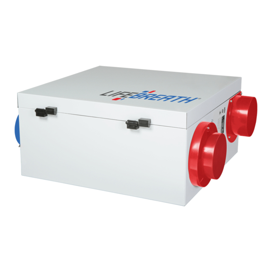
DIMENSIONS 200 ERV inches (mm) * All Duct Connections 6"(150mm) MOTOR STALE AIR FRESH AIR FROM INSIDE TO INSIDE FILTERS BLOWERS *NOTE: Front clearance of 25 inches (635 mm) STALE AIR is recommended FRESH AIR TO OUTSIDE for servicing unit. FROM OUTSIDE 31"... -
Page 12: Operation Of The Controlair 15
PART 1 FUNCTION & CONTROL Models 200 & 500 Only Operating the ControlAir 15 Self Test Plugging in the ERV energizes the unit. A self test function Each time the ERV is powered/energized the self test function will be performed every time the ERV is energized (refer to will automatically initiate. - Page 13 To select mode of operation for ControlAir 15 Press and hold the fan selection button on the Control Pad. After 5 seconds the control will begin to cycle each mode holding each for 2 seconds. Release the button when the desired mode of operation is reached.
-
Page 14: Optional Remote Controls
ControlAir 15 OPTIONAL REMOTE CONTROLS Models 200 & 500 Only AIR SENTRY™ AIR QUALITY SENSOR PROGRAMMABLE VENTILATION CONTROLLER (PVC) LOCATION: Hallway, kitchen, office LOCATION: Kitchen, basement, & work place (connect 1/unit only) work place (connect 1/unit only). • Advanced digital remote. •... -
Page 15: Speed Selection And Controls
Speed Selection and Controls Model 700 and 1200 ERV only from high to low from a remote location. To wire the unit in These models are equipped with a 3 speed control, low this configuration you would need two electrical on/off medium and high, as well as a lighted on/off switch and a switches to be installed at the remote location into a dou- 4 screw terminal strip. -
Page 16: Installation
PART 2 INSTALLATION Model 200 only Location WARNING: The ERV must be located in a conditioned space where it In order to prevent electric shock when cleaning or ser- will be possible to conveniently service the unit. Typically vicing the ERV, it is extremely important to confirm the the ERV would be located in the mechanical room or an polarity of the power line that is switched by the safety area close to the outside wall where the weatherhoods... -
Page 17: Installing Air Ducts
INSTALLING AIR DUCTS • At least 3' (1 m) away from the corner of the building • Not near a gas meter, electric meter or a walkway where fog or ice could create a hazard A well designed and installed ducting system will allow the •... -
Page 18: Connections To Furnace Ductwork
SUPPLY AIR DUCTING Dampers and Grilles In homes without a forced air furnace (see Fig. 7), fresh air should The use of balancing dampers and/or adjustable grilles to bal- be supplied to all bedrooms and living areas, excluding bath- rooms, kitchen and utility areas. It should be supplied from high ance the flow rates into various rooms is recommended. -
Page 19: Air Flow Balancing And Procedure
PITOT TUBE AIR FLOW BALANCING It is necessary to have balanced air flows in an ERV. The volume of air brought This is an example for determining the airflow in a 6” duct. in from the outside must equal the volume of air exhausted by the unit. If the air The Pitot tube reading was 0.025 inches of water. -
Page 20: Installation Diagrams
Installation Diagrams (Examples Only) Round adjustable TECHGRILLES Optional controls for intermittent high speed ERV access door (on back of unit) Optional control Figure 6 Independent Installation Adjustable fresh Adjustable stale Adjustable damper for air supply air return balancing air flow in and out of the house Stale air exhaust hood... -
Page 21: Installation Diagrams
Installation Diagrams (Examples only) DIRECT CONNECTION of the SUPPLY AIR STREAM to the FURNACE COLD AIR RETURN EXHAUST AIR from various parts of home. i.e. bathrooms (if required), kitchens (if required). Return Air Balancing damper* in both air streams. 3' min. recommended Outdoors Cool Air... -
Page 22: General Installation
INSTALLATION MODEL 500, 700, AND 1200 ONLY Location for Mounting The Ductwork System The ERV must be located in a conditioned space A properly designed ducting system will allow the where the surrounding air temperature does not ERV to operate at its maximum efficiency. (Air flow effect the ERV or its ducting. -
Page 23: Stale Air Return System
Outside Weatherhoods Stale Air Return System The weatherhoods must have built-in “bird” screen with 1/4 in The stale air return system is used to draw air from the (63.5 mm) minimum mesh to prevent birds and rodents from points in the building where the worst air quality problems entering into the ductwork. -
Page 24: Fresh Air Supply System
Fresh Air Supply System The Integrated HVAC System The fresh air supply ductwork from the ERV may be The ERV has become an integral component of the directly connected to the return air duct of the forced air HVAC system. Figure A shows an ERV unit providing system. - Page 25 ECONOMIZER (DISABLED) ROOFTOP UNIT SUPPLY DUCT RETURN AIR DUCT or BREATHER T STALE AIR ERV UNIT EXHAUST B.D. B.D. FRESH AIR ERV FRESH SUPPLY AIR SUPPLY STALE AIR EXHAUST TO ERV Figure 6A ECONOMIZER (DISABLED) ROOFTOP UNIT ROOF DECK 12" BREATHER CEILING RETURN AIR PLENUM SUPPLY DUCTWORK SPACE...
-
Page 26: Various Installation Types
Various Installation Types *NOTE: When installing your ERV, Figure 7A flexible duct connectors should Saddle Installation be installed between the ERV and the galvanized ductwork. Vibration Isolators (Supplied by others) Threaded rod and U channel (Supplied by others) Hang unit with suspended rods Figure 7B and "U"... -
Page 27: Troubleshooting Your Erv
TROUBLESHOOTING YOUR ERV SYSTEM Symptom Cause Solution • Clean exterior hoods or vents Poor air flow • Mesh on outside hood is plugged • Remove and clean filters • Filters plugged • Remove and clean core (vacuum or blow out; •... -
Page 28: Maintenance Routine
Maintenance Routine (1) Inspect Exterior Hoods at least once a month (6) General Maintenance - Twice a Year Make sure exhaust and fresh air supply hoods are not blocked Wipe down the inside of the cabinet with a damp cloth to up or restricted by leaves, grass or dirt. -
Page 29: Wiring Diagram
HRV RESIDENTIAL RESIDENTIAL ERV WIRING WIRING DIAGRAM MICRO PROCESSOR BOARD THERMIST0R TO DISABLE RECIRCULATION INTERNAL REMOVE SEL2 DEHUMIDISTAT SEL2 Note: All control connections REMOVE SEL1 FOR R-2000 are labeled by colour. SEL1 Connect to corresponding colour with low voltage wire ( 20 gauge minimum). - Page 30 WIRING DIAGRAM 500 (DAMPER DEFROST) MICRO PROCESSOR BOARD THERMIST0R TO DISABLE RECIRCULATION INTERNAL REMOVE SEL2 DEHUMIDISTAT SEL2 Note: REMOVE SEL1 All control connections FOR R-2000 SEL1 are labeled by colour. Connect to corresponding colour with low voltage wire ( 20 gauge minimum). COMMON CONTACT CONTROLAIR 15...
-
Page 32: Tfp Information
- Nutech’s ULTIMATE Air Cleaner System TURBULENT FLOW PRECIPITATOR AIR CLEANER Features & Benefits • Cleans home of airborne particles down to 0.1 microns for up to 5 years with little or no mainte- nance. • Removes 99.9% of all allergy and hay fever causing pollen and spores. •...
Need help?
Do you have a question about the 200ERV and is the answer not in the manual?
Questions and answers