Table of Contents
Advertisement
Advertisement
Chapters
Table of Contents

Related Manuals for Digium series G11


Summary of Contents for Digium series G11
- Page 1 Gateway Series G100 / G200 / G400 / G800 Administrator Manual 601-00020 Rev. B...
- Page 2 Digium, Inc. 445 Jan Davis Drive Huntsville, AL 35806 United States Main Number: +1 (256)-428-6000 Tech Support: +1 (256)-428-6161 U.S. Toll Free: +1 (877)-344-4861 Sales: +1 (256)-428-6262 www.digium.com www.asterisk.org www.asterisknow.org © Digium, Inc. 2013 All rights reserved. No part of this publication may be copied, distributed, transmitted, transcribed, stored in a retrieval system, or translated into any human or computer language without the prior written permission of Digium, Inc.
- Page 3 Compliance Information Compliance information for this product is available at http://www.digium.com/compliance. Digium, Inc. Page 3...
- Page 4 Introduction to Gateway Series Documentation This manual contains product information for the Gateway Series appliances. Be sure to refer to any supplementary documents or release notes that were shipped with your equipment. The manual is organized in the following manner:...
- Page 5 Symbol Definitions Caution statements indicate a condition where damage to the unit or its configuration could occur if operational procedures are not followed. To reduce the risk of damage or injury, follow all steps or procedures as instructed. The ESD symbol indicates electrostatic sensitive devices. Observe precautions for handling devices.
-
Page 6: Important Safety Instructions
Important Safety Instructions Servicing. Do not attempt to service this unit. There are no user-serviceable parts inside. Refer servicing to qualified service personnel. Batteries. The batteries in the unit are not user-serviceable. Refer servicing to qualified service personnel. CAUTION - Risk of explosion if battery is replaced by an incorrect type. -
Page 7: Table Of Contents
Hardware Installation ........24 Connecting to the Gateway Series ......33 Chapter 3 Configuration . - Page 8 Table Of Contents Appendix A Pin Assignments ......... 85 Appendix B Specifications .
- Page 9 List of Figures Figure 1: TDM PBX to VoIP Scenario ....13 Figure 2: VoIP PBX to TDM Scenario ....13 Figure 3: TDM PBX to TDM and VoIP Scenario .
- Page 10 List of Tables Table 1: Gateway Series Models..... . 23 Table A-1: Gigabit Ethernet Port Pinouts ....85 Table A-2: RJ45 T1/E1 Port Connector.
-
Page 11: Overview
Chapter 1 Overview Digium's Gateway Series is a converged media gateway product line designed to interface between TDM (T1/E1) and IP networks (SIP). The Gateway Series connects legacy telephone systems to IP networks and seamlessly integrates VoIP PBXs with the PSTN. Powered by innovative hardware and software solutions, Digium’s Gateway Series are managed... - Page 12 FXO and FXS (T1 only) – Ground Start – Loop Start – Loop Start with Disconnect Detect (Kewlstart) Example scenarios utilizing the Gateway Series are illustrated in Figure 1, Figure 2, and Figure 3. Digium, Inc. Page 12...
-
Page 13: Figure 1: Tdm Pbx To Voip Scenario
Chapter 1: Overview Figure 1: TDM PBX to VoIP Scenario Figure 2: VoIP PBX to TDM Scenario Digium, Inc. Page 13... -
Page 14: Figure 3: Tdm Pbx To Tdm And Voip Scenario
Chapter 1: Overview Figure 3: TDM PBX to TDM and VoIP Scenario Digium, Inc. Page 14... -
Page 15: Echo-Cancellation
128ms of echo cancellation across all channels and provides a G.168 compliant echo cancellation solution. If not explicitly disabled in the Gateway Series web GUI, the hardware- based echo canceller will automatically operate and cancel all network echo within its tail range (1024 taps). -
Page 16: Unit Installation
Unit Identification on page 23 Hardware Installation on page 24 Note: The Gateway Series appliance installation instructions are written so that they will apply to any model in the series. Examples and model specific information are included as needed. Digium, Inc. - Page 17 Chapter 2: Unit Installation Unpacking the Unit When you unpack your unit, carefully inspect it for any damage that may have occurred in shipment. If damage is suspected, file a claim with the carrier and contact the reseller from which the unit was purchased. If the unit was purchased directly from Digium, contact Digium Technical Support at +1 (256)-428-6161.
-
Page 18: Shipment Inspection
Chapter 2: Unit Installation Shipment Inspection The following items are included in shipment of a Gateway Series appliance: Gateway Series appliance Power cord with attached T1/E1 loopback plug Mounting brackets (2 each) Bracket mounting screws, #8-32 black truss head, Phillips, 3/16”... -
Page 19: Front Panel Identification
Chapter 2: Unit Installation Front Panel Identification This section describes the components on the front panel of the Gateway Series models. USB Recovery T1/E1 Gigabit Status Ethernet Device Ethernet Status T1/E1 Status Port Figure 4: G100 Single Port Appliance Digium, Inc. -
Page 20: Figure 5: G200 Dual Port Appliance
Chapter 2: Unit Installation USB Recovery T1/E1 Gigabit Status Ethernet Device Ethernet Status T1/E1 Status Port Figure 5: G200 Dual Port Appliance Digium, Inc. Page 20... -
Page 21: Figure 6: G800 Octal Port Appliance
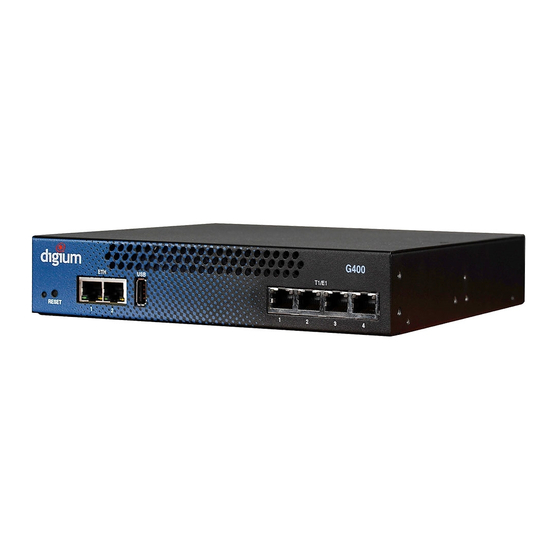
T1/E1 Status Port Figure 6: G800 Octal Port Appliance Device Status - This LED corresponds to the status of the Gateway Series appliance. See Frequently Asked Questions on page 80 for more information. Gigabit Ethernet - The 10/100/1000BaseT Ethernet port(s) provides ... - Page 22 See Frequently Asked Questions on page 80 for more infor mation. Reset Switch (G400/G800 only) - This recessed switch is used to restart the Gateway Series appliance or reset its GUI password. See Frequently Asked Questions on page 80 for more information. Digium, Inc. Page 22...
-
Page 23: Unit Identification
Chapter 2: Unit Installation Unit Identification The defining characteristic of the Gateway Series models are the number of T1/E1 and Ethernet ports supported. See Table 1 for a list of the various models. Table 1: Gateway Series Models Model Type... -
Page 24: Hardware Installation
Chapter 2: Unit Installation Hardware Installation This section describes how to properly install the hardware for a Gateway Series appliance. Caution Only qualified service personnel should continue with hardware installation and configuration of the Gateway Series appliance. Users should not attempt to perform these functions themselves. - Page 25 Important Use only a grounded electrical outlet when connecting the Gateway Series appliance to a power source. If you do not know whether the outlet is grounded, consult with a qualified electrician.
- Page 26 The included hardware allows the Gateway Series appliance to be wall mounted, rack mounted side-by-side with another Gateway Series appliance, or placed flat on a level surface. If a single Gateway Series appliance is to be rack mounted, the optional long mounting bracket (not supplied, part number 3244-00042) must be used.
- Page 27 Single Unit Rack Mount: In order to rack mount the Gateway Series appliance by itself, place one of the short mounting brackets on the front of one side of the Gateway Series appliance. Line up the holes from the mounting bracket to the threaded holes on the front side of the Gateway Series appliance.
- Page 28 In order to rack mount the Gateway Series appliance side-by-side with another Gateway Series appliance, place one of the short mounting brackets on the front of the left side of the first Gateway Series appliance. Line up the holes from the mounting bracket to the threaded holes on the front of the left side of the first Gateway Series appliance.
-
Page 29: Figure 7: Side-By-Side Rack Mounting
Gateway Series appliance as shown in Figure 8 on page 30. The unit should be mounted at or below eye level to properly view the LEDs. -
Page 30: Figure 8: Acceptable Wall Mount Orientation
Chapter 2: Unit Installation If the Gateway Series appliance is placed in the “right side down” orientation, the 2 remaining #8 black truss head mounting screws should be fully inserted into the screw holes near the front of the right side of the Gateway Series appliance. - Page 31 Chapter 2: Unit Installation Level Surface: In order to place the Gateway Series appliance flat on a level surface, the rubber feet should be adhered to the 4 corners of the bottom of the Gateway Series appliance. This will help secure the Gateway Series appliance to the surface it is placed on.
- Page 32 Chapter 2: Unit Installation Connecting Ports A description of each of the front panel connectors on a Gateway Series appliance is available in the section titled Front Panel Identification on page 19. Please refer to that section to determine what should be connected to each connector.
-
Page 33: Connecting To The Gateway Series
Connecting via DHCP assigned IP address 1. If a DHCP server exists on the network that the Gateway Series appli ance will be placed on, connect one end of an Ethernet cable to the Gateway Series appliance's first Ethernet port, and the other end to an Ethernet connection on a network switch or hub. - Page 34 Gateway Series appliance. See IP Configuration on page 36. Connecting via Statically assigned IP address 1. If a DHCP server does not exist on the network that the Gateway Series appliance will be placed on, connect one end of an Ethernet cable to the Gateway Series appliance's first Ethernet port, and the other end to an Ethernet connection on a computer.
- Page 35 The default IP address for the Gateway Series web GUI is 192.168.69.1. The default username for the Gateway Series web GUI is admin, and the default password is admin. 3. It is highly recommended that the admin password be changed using the System Administrators menu on the web GUI.
-
Page 36: Figure 9: Ip Configuration Menu For G100 / G200
Chapter 2: Unit Installation IP Configuration The general networking and configuration server options in the Gateway Series web GUI should be configured before others. The IP configuration menus for the G100 and G200 models differ from those of the G400 and G400 models. - Page 37 Note: It is recommended that this feature be disabled if the DHCP server is not configured to always provide the same IP address based on MAC address. If this is the case, the Gateway Series appliance’s network settings should be manually configured. The MAC addresses of the Gateway Series appliance are printed on a label on the back of the unit.
- Page 38 DNS Addresses - If Obtain an IP Address via DHCP is disabled, specify up to 3 DNS servers to be used by the Gateway Series appli ance. A DNS server may also be referred to as a nameserver. Also Continue Using Default Install IP Address - Leaving this ...
- Page 39 Address via DHCP is enabled and the DHCP server specifies the path and configuration database file on the configuration server using Option 66, this feature may be enabled for all Gateway Series configu ration settings to be automatically configured using a configuration server.
-
Page 40: Figure 10: Ip Configuration Menu For G400 / G800
Figure 10: IP Configuration Menu for G400 / G800 The General Networking Options for the G400 and G800 models are described below. Hostname - Specify the hostname of the Gateway Series appliance. If a hostname is specified, the Gx00-aa-bb-cc hostname will no longer be configured. - Page 41 Also Continue Using Default Install IP Address - Leaving this option enabled will allow the Gateway Series appliance to listen for network requests on its factory default IP address. Note: For security purposes, it is recommended that this feature be disabled after initial IP configuration is complete.
- Page 42 Address via DHCP is enabled on an Interface tab and a DHCP server specifies the path and configuration database file on the configuration server using Option 66, this feature may be enabled for all Gateway Series configuration settings to be automatically configured using a configuration server.
- Page 43 Note: It is recommended that this feature be disabled if the DHCP server is not configured to always provide the same IP address based on MAC address. If this is the case, the Gateway Series appliance’s network settings should be manually configured. The MAC addresses of the Gateway Series appliance are printed on a label on the back of the unit.
- Page 44 Gateway Series appliance. The gateway address is usually the address of the router on the network. Static Routes - This option can be used to force the Gateway Series appliance to use a specific gateway interface to reach specific net...
-
Page 45: Configuration
Context-sensitive help buttons are provided above most sections of the Gateway Series web GUI. Clicking on a help button will open a new window which contains a detailed description of the options available for that section. -
Page 46: Figure 11: Login Screen
The Gateway Series appliance should already be connected to your network or computer, as described in Connecting to the Gateway Series on page 33. Using a Gateway Series supported web browser, open a browser window and enter the IP address for the Gateway Series appliance using HTTPS (e.g. - Page 47 It is highly recommended that the admin password be changed using the System Administrators menu on the web GUI. In addition, it is highly recommended that the software on a Gateway Series appliance be updated to the latest version before proceeding with configuration. See Software Updates on page 74.
-
Page 48: Figure 12: Main Menu
Chapter 3: Configuration The Gateway Series web GUI is divided into the following main sections. Settings and Configuration on page 49 Logging and Reporting on page 65 Status and Diagnostics on page 66 Maintenance on page 72 ... -
Page 49: Settings And Configuration
Chapter 3: Configuration Settings and Configuration This section provides the ability to configure SIP and TDM settings, create call routing groups and rules, manage system administrators, and set up networking. Included are the following sections. SIP Endpoints on page 50 ... -
Page 50: Sip Endpoints
This section provides the ability to add and modify SIP endpoints, and configure call, media, and fax settings. A SIP endpoint will typically be a SIP PBX or SIP provider connected to the Gateway Series appliance. Included are the following sections. - Page 51 Chapter 3: Configuration – DTMF Mode – Trust Remote-Party-ID – Send Remote-Party-ID – Caller ID Presentation – Progress Inband – Allow Overlap Dialing – Append user=phone to URI – Add Q.850 Reason Headers – Honor SDP Version – Allow Transfers –...
- Page 52 Chapter 3: Configuration – G.726 – G.729 – GSM – Codec Priority – ALAW Packetization Rate – ULAW Packetization Rate – GSM Packetization Rate – G.722 Packetization Rate – G.726 Packetization Rate – G.726 Nonstandard – G.729 Packetization Rate – Use Preferred Codec Only Fax Settings (Advanced) - Fax related settings.
-
Page 53: Global Sip Settings
Chapter 3: Configuration Global SIP Settings This section provides the ability to add and modify global SIP settings. These settings are for experienced administrators only. Please take care when modifying any of these settings. The default values should be sufficient for most applications. Included are the following sections. Networking - General, NAT, RTP, RTCP, and DTMF settings. - Page 54 Chapter 3: Configuration – Send Compact Headers – SDP Owner – Disallowed SIP Methods – Shrink Caller ID – Maximum Registration Expiry – Minimum Registration Expiry – Default Registration Expiry – Registration Timeout – Number of Registration Attempts Security - SIP domains and authentication settings. The following set ...
- Page 55 Chapter 3: Configuration – UDPTL FEC Span – Use Only Even Numbered Ports Digium, Inc. Page 55...
-
Page 56: T1/E1
Chapter 3: Configuration T1/E1 This section provides the ability to configure the T1/E1 hardware in the Gateway Series appliance. Included are the following sections. General - General options for T1/E1 configuration. The following set tings are available. – Locale –... - Page 57 Chapter 3: Configuration – PRI Dial Plan for Dialing Number – International Prefix – National Prefix – Local Prefix – Private Prefix – Unknown Prefix – Network Specific Facility (NSF) Messages – Idle Bearer Reset – Idle Bearer Reset Period –...
- Page 58 Chapter 3: Configuration – Connect Acknowledge - T313 – Answer on Polarity Switch – Hangup on Polarity Switch – Polarity on Answer Delay – Pre-Wink Time – Wink Time – Start Time – Receiver Wink Time – Pre-Flash Time – Flash Time –...
-
Page 59: Call Routing Groups
Chapter 3: Configuration Call Routing Groups This section provides the ability to add and modify SIP and T1/E1 call routing groups. A call routing group allows a group of channels to be addressed when creating a call routing rule. The following settings are available. -
Page 60: Call Routing Rules
Chapter 3: Configuration Call Routing Rules This section provides the ability to add and modify call routing rules. A call routing rule determines how a call is handled based upon certain characteristics such as inbound channel and DID. It is also possible to manipulate matched numbers before connecting outbound calls. - Page 61 Chapter 3: Configuration System Administrators This section provides the ability to add and modify system administrators for access to the Gateway Series web GUI. The following settings are available. Full Name Username Email Address Password Password Confirmation ...
- Page 62 Chapter 3: Configuration IP Configuration This section provides the ability to configure IP options for the Gateway Series appliance. See IP Configuration on page 36 for more information. The following settings are available. Hostname Obtain an IP Address via DHCP ...
- Page 63 Chapter 3: Configuration HTTPS This section provides the ability to supply your own certificate for secure connection to the Gateway Series web GUI. A self-signed certificate is provided by default. The following settings are available. X.509 Certificate in PEM Format ...
- Page 64 Chapter 3: Configuration Access Control This section provides the ability to limit access to the web GUI and SIP traffic through the Gateway Series appliance. All other protocols are blocked. The following settings are available. Rule Name Network ...
-
Page 65: Logging And Reporting
Chapter 3: Configuration Logging and Reporting This section provides the ability to configure and view system statistics and logging of the Gateway Series appliance. Included are the following sections. Statistics - Displays statistics for active calls and calls processed, and ... -
Page 66: Status And Diagnostics
Chapter 3: Configuration Status and Diagnostics This section provides the ability to view connection status, system information, perform advanced debugging, and troubleshoot problems with diagnostic tools. Included are the following sections. Connection Status on page 67 System Information on page 68 ... -
Page 67: Connection Status
Chapter 3: Configuration Connection Status This section provides the ability to view the connection status of network interfaces, SIP endpoints, and T1/E1 interfaces. Included are the following sections. Network - Status of network interfaces SIP Endpoints - Status of SIP endpoints ... -
Page 68: System Information
Chapter 3: Configuration System Information This section provides the ability to view system information on the Gateway Series appliance, including model number, software version, MAC addresses, uptime, system time, and system temperature. Digium, Inc. Page 68... -
Page 69: Diagnostic Tests
Chapter 3: Configuration Diagnostic Tests This section provides the ability to test the operation of the Gateway Series appliance. For example, the loopback test will run a pattern loop test to verify the integrity of a T1/E1 port. See Chapter 4—... -
Page 70: Advanced Debugging
Debugging Sessions in Progress - Displays existing logs or recording sessions in progress Start a New Debugging Session - TCP traffic, gateway logging, and system logging settings for starting a new debugging session. The fol lowing settings are available. -
Page 71: Technical Support
Chapter 3: Configuration Technical Support This section provides the ability to enable remote access for Digium Support Personnel to access the Gateway Series appliance for support purposes. The following settings are available. Change Remote Access Status to Username ... -
Page 72: Maintenance
Chapter 3: Configuration Maintenance This section provides the ability to perform configuration backups, perform system updates, set the system clock, reboot, and restore factory settings. Included are the following sections. Backups on page 73 Software Updates on page 74 ... - Page 73 Chapter 3: Configuration Backups This section provides the ability to create and restore a backup. Included are the following sections. Download Backup - Download a backup in database format Note: At least one configuration change must be made before a backup can be generated and downloaded.
- Page 74 This section provides the ability to perform a software update for the Gateway Series appliance. If the Gateway Series appliance is connected to the Internet, you will be prompted if there is a newer version of the software available, and offered to automatically download and install it.
- Page 75 Chapter 3: Configuration System Clock This section provides the ability to set the system clock on the Gateway Series appliance and to sync it against a network time server. The following settings are available. Timezone Time Set Method ...
- Page 76 This section provides the ability to perform a system reboot, system shutdown, or factory reset of the Gateway Series appliance. A system shutdown will drop all current calls and cause the Gateway Series appliance to become unreachable by any method except physical access.
-
Page 77: Troubleshooting
Chapter 4 Troubleshooting This chapter provides information regarding troubleshooting tools, frequently asked questions, and possible resolutions as identified by Digium Technical Support. Multiple resources are available to obtain more information about Asterisk and Digium products. Please visit both www.digium.com and www.asterisk.org for more information. Digium, Inc. - Page 78 (i.e. parent) directory of an empty USB flash drive. Note: A USB flash drive is not provided with a Gateway Series appliance. It must be purchased separately. The USB flash drive should be at least 2GB in size and formatted with the FAT32 filesystem.
- Page 79 Then it will turn amber for less than a minute. Next, it will run red for about 2 minutes. Lastly, the Device Status LED will remain off. At this point, it is safe to power off the Gateway Series appliance. Remove the USB flash drive and power cycle the Gateway Series appliance.
-
Page 80: Frequently Asked Questions
Blinking Red (right side) - It is normal for this LED to constantly blink as long as the Gateway Series Appliance is powered on. Singular Blinking Green (right side) - Line has been placed into ... - Page 81 Chapter 4: Troubleshooting What type of cable do I need for the T1/E1 ports on a Gateway Series appliance? A straight-through RJ45 T1/E1 cable is needed for connecting to the RJ45 ports on a Gateway Series appliance when connecting to the PSTN. If connecting to a TDM PBX, a crossover RJ45 T1/E1 cable may be required.
- Page 82 Chapter 4: Troubleshooting The Gateway Series GUI password can be reset to its default without modifying any configuration settings by following the steps described below. 1. Press the reset switch once. 2. The status LED will start flashing amber. 3. Press the reset switch again while the status LED flashes amber.
- Page 83 Chapter 4: Troubleshooting Where can I find answers to additional questions? Digium Technical Support (+1 256-428-6161), or Toll Free in the U.S. (+1 877-344-4861), is available 7am-8pm Central Time (GMT -6), Monday - Friday. Please refer to Free Installation Support on page 84 for additional information on how to obtain assistance from Digium Technical Support.
-
Page 84: Free Installation Support
Chapter 4: Troubleshooting Free Installation Support Digium hardware products include free installation support. In order to receive this support, register your Digium product using the serial number located on the serialization label of your Digium unit. Steps to receive installation support: 1. Record your product serial number. -
Page 85: Pin Assignments
Appendix A Pin Assignments All RJ45 (8P8C) ports labeled ETH on the Gateway Series appliance are 8-pin. The pin assignments are identified i n Table A-1. Note: Category 5e or Category 6 cables are required for Gigabit (1Gbps) operation up to 100 meters. Category 5 cables will work for short runs, but the link speed may be limited over long distances. -
Page 86: Table A-2: Rj45 T1/E1 Port Connector
Appendix A: Pin Assignments All RJ45 (8P8C) ports labeled T1/E1 on the Gateway Series appliance are 8-pin. RJ45 jacks are also commonly referred to as RJ48 when used for telecommunication. The pin assignments are identified in Table A-2. Table A-2: RJ45 T1/E1 Port Connector... -
Page 87: Specifications
Appendix B Specifications This appendix provides specifications, required environmental conditions, and maximum power consumption for the Gateway Series appliances. Physical (All Units). Size: 8.6” × 9.0” × 1.72” (21.84 x 22.86 x 4.37 cm) Weight: 2 lbs 12 oz (1,247.38 gm) Interfaces. - Page 88 Appendix B: Specifications Power: For G100/G200, 10W maximum, 7.5W typical. For G400/ G800, 15W maximum, 12W typical. Digium, Inc. Page 88...
-
Page 89: Glossary And Acronyms
Appendix C Glossary and Acronyms 8P8C 8 position 8 conductor Module connector commonly used to terminate twisted pair. ANSI American National Standards Institute An organization which proposes and establishes standards for international communications. asynchronous Not synchronized; not timed to an outside clock source. Transmission is controlled by start bits at the beginning and stop bits at the end of each character. - Page 90 Appendix C: Glossary and Acronyms bits per second A measurement of transmission speed across a data connection. Basic Rate ISDN broadband Broadband transmission shares the bandwidth of a particular medium (copper or fiber optic) to integrate multiple signals. The channels take up different frequencies on the cable, integrating voice, data, and video over one line.
- Page 91 Appendix C: Glossary and Acronyms CLEC Competitive Local Exchange Carrier A term for telephone companies established after the Telecommunications Act of 1996 deregulated the LECs. CLECs compete with ILECs to offer local service. See also LEC and ILEC. Central Office The CO houses local switching equipment.
- Page 92 Appendix C: Glossary and Acronyms Digital Signal, Level 1 1.544 Mbps in North America (T1) and Japan (J1) -up to 24 voice channels (DS0s), 2.048 Mbps in Europe (E1) - up to 32 voice channels (DS0s). DS1/T1/E1 lines are part of the PSTN. Digital Signal, Level 3 T3 in North America and Japan, E3 in Europe.
- Page 93 Appendix C: Glossary and Acronyms Foreign Exchange Office Receives the ringing voltage from an FXS device. Outside lines are connected to FXO ports. Foreign Exchange Station Initiates and sends ringing voltage. Phones are connected to FXS ports. G.711 A recommendation by the Telecommunication Standardization Sector (ITU-T) for an algorithm designed to transmit and receive mulaw PCM voice and A-law at a digital bit rate of 64 kbps.
- Page 94 Appendix C: Glossary and Acronyms HDLC High-Level Data Link Control A bit-oriented synchronous data link layer protocol developed by the International Organization for Standardization (ISO). Inter-Asterisk eXchange The native VoIP protocol used by Asterisk. It is an IETF standard used to enable VoIP connections between Asterisk servers, and between servers and clients that also use the IAX protocol.
- Page 95 A state in which the transmit signal is reversed back as the receive signal, typically by a far end network element. MGCP Media Gateway Control Protocol multiplexing Transmitting multiple signals over a single line or channel. FDM (frequency division multiplexing) and TDM (time division multiplexing) are the two most common methods.
- Page 96 Appendix C: Glossary and Acronyms Network Termination A device connecting the customer's telephone or data equipment to the local ISDN exchange carrier's line. NT devices are connected to TE devices. Private Branch Exchange A smaller version of a phone company’s large central switching office. Example: Asterisk.
- Page 97 Appendix C: Glossary and Acronyms Primary Rate ISDN PSTN Public Switched Telephone Network A communications network which uses telephones to establish connections between two points. Also referred to as the dial network. PTMP Point-to-Multipoint A connection where data is broadcast between more than two endpoints. Point-to-Point A connection restricted to two endpoints.
- Page 98 Appendix C: Glossary and Acronyms RJ11 A six-pin jack typically used for connecting telephones, modems, and fax machines in residential and business settings to PBX or the local telephone CO. RJ45 8P8C, un-keyed modular connector type for Ethernet over twisted pair. Predominantly used in LAN and uses Unshielded Twisted Pair cable.
- Page 99 Appendix C: Glossary and Acronyms Time Division Multiplexer A device that supports simultaneous transmission of multiple data streams into a single high-speed data stream. TDM combines signals by interleaving bits one after the other. Terminal Equipment A device that is established as a point of termination of a communications circuit or channel.
- Page 100 Appendix C: Glossary and Acronyms Volts VoIP Voice over Internet Protocol Technology used for transmitting voice traffic over a data network using the Internet Protocol. Digium, Inc. Page 100...
Need help?
Do you have a question about the series G11 and is the answer not in the manual?
Questions and answers