Digium G100 SERIES Administrator's Manual
Hide thumbs
Also See for G100 SERIES:
- Administrator's manual (100 pages) ,
- Administrator's manual (73 pages)
Table of Contents
Advertisement
Quick Links
Advertisement
Chapters
Table of Contents

Related Manuals for Digium G100 SERIES


Summary of Contents for Digium G100 SERIES
- Page 1 Gateway Series G100 / G200 / G400 / G800 Administrator Manual 601-00020 Rev. B...
- Page 2 Digium, Inc. Digium, Inc. has made every effort to ensure that the instructions contained in this document are adequate and error free. The manufacturer will, if necessary, explain issues which may not be covered by this documentation.
- Page 3 Compliance Information Compliance information for this product is available at http://www.digium.com/compliance. Digium, Inc. Page 3...
- Page 4 Explains resolutions to common problems and frequently asked questions pertaining to unit installation and usage. Pin Assignments Describes the states supported by the unit. Specifications Details unit specifications. Glossary and Defines terms related to this product. Acronyms Digium, Inc. Page 4...
- Page 5 (ESD) wrist strap while handling the device. The Electrical Hazard Symbol indicates a possibility of electrical shock when operating this unit in certain situations. To reduce the risk of damage or injury, follow all steps or procedures as instructed. Digium, Inc. Page 5...
- Page 6 To reduce the risk of damaging the unit or your equipment, do not attempt to open the enclosure or gain access to areas where you are not instructed to do so. Refer servicing to qualified service personnel. Save these instructions for future reference. Digium, Inc. Page 6...
-
Page 7: Table Of Contents
Free Installation Support ....... . .84 Digium, Inc. Page 7... - Page 8 Glossary and Acronyms ........89 Digium, Inc.
- Page 9 Figure 12: Main Menu ....... . 48 Digium, Inc. Page 9...
- Page 10 Gigabit Ethernet Port Pinouts ....85 Table A-2: RJ45 T1/E1 Port Connector....86 Digium, Inc. Page 10...
-
Page 11: Overview
Chapter 1 Overview Digium's Gateway Series is a converged media gateway product line designed to interface between TDM (T1/E1) and IP networks (SIP). The Gateway Series connects legacy telephone systems to IP networks and seamlessly integrates VoIP PBXs with the PSTN. Powered by innovative hardware and software solutions, Digium’s Gateway Series are managed... - Page 12 – Feature Group D FXO and FXS (T1 only) – Ground Start – Loop Start – Loop Start with Disconnect Detect (Kewlstart) Example scenarios utilizing the Gateway Series are illustrated in Figure 1, Figure 2, and Figure 3. Digium, Inc. Page 12...
-
Page 13: Figure 1: Tdm Pbx To Voip Scenario
Chapter 1: Overview Figure 1: TDM PBX to VoIP Scenario Figure 2: VoIP PBX to TDM Scenario Digium, Inc. Page 13... -
Page 14: Figure 3: Tdm Pbx To Tdm And Voip Scenario
Chapter 1: Overview Figure 3: TDM PBX to TDM and VoIP Scenario Digium, Inc. Page 14... -
Page 15: Echo-Cancellation
G.168 compliant echo cancellation solution. If not explicitly disabled in the Gateway Series web GUI, the hardware- based echo canceller will automatically operate and cancel all network echo within its tail range (1024 taps). Digium, Inc. Page 15... -
Page 16: Unit Installation
Unit Identification on page 23 Hardware Installation on page 24 Note: The Gateway Series appliance installation instructions are written so that they will apply to any model in the series. Examples and model specific information are included as needed. Digium, Inc. Page 16... -
Page 17: Unpacking The Unit
If damage is suspected, file a claim with the carrier and contact the reseller from which the unit was purchased. If the unit was purchased directly from Digium, contact Digium Technical Support at +1 (256)-428-6161. Keep the original shipping container to use for future shipment or proof of damage during shipment. -
Page 18: Shipment Inspection
Note: After inspecting the shipment, Digium requires that the appliance be registered for support eligibility. Unregistered appliances are not eligible for Digium support. Please refer to Free Installation Support on page 84 for additional information on how to obtain assistance from Digium Technical Support. -
Page 19: Front Panel Identification
Chapter 2: Unit Installation Front Panel Identification This section describes the components on the front panel of the Gateway Series models. Recovery T1/E1 Gigabit Status Ethernet Device Ethernet Status T1/E1 Status Port Figure 4: G100 Single Port Appliance Digium, Inc. Page 19... -
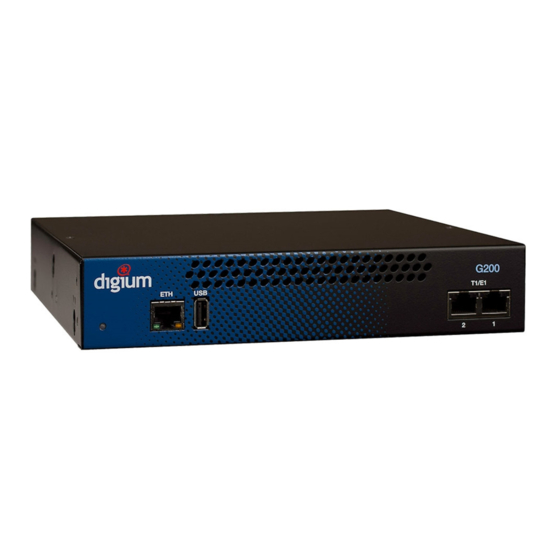
Page 20: Figure 5: G200 Dual Port Appliance
Chapter 2: Unit Installation Recovery T1/E1 Gigabit Status Ethernet Device Ethernet T1/E1 Status Status Port Figure 5: G200 Dual Port Appliance Digium, Inc. Page 20... -
Page 21: Figure 6: G800 Octal Port Appliance
RJ45 interface and supports Auto- MDIX. It is used to pass Ethernet packetized voice and web manage- ment data between the Gateway Series and the network. See Gigabit Ethernet Port Pinouts on page 85 for more information. Digium, Inc. Page 21... - Page 22 See Frequently Asked Questions on page 80 for more infor- mation. Reset Switch (G400/G800 only) - This recessed switch is used to restart the Gateway Series appliance or reset its GUI password. See Frequently Asked Questions on page 80 for more information. Digium, Inc. Page 22...
-
Page 23: Unit Identification
The defining characteristic of the Gateway Series models are the number of T1/E1 and Ethernet ports supported. See Table 1 for a list of the various models. Table 1: Gateway Series Models Model Type T1/E1 Ports Ethernet Ports G100 T1/E1 G200 T1/E1 G400 T1/E1 G800 T1/E1 Digium, Inc. Page 23... -
Page 24: Hardware Installation
The wire length should be as short as possible, and gauge should be 18 AWG or greater. Stranded or solid wire is acceptable. Wire is not provided with the Gateway Series Digium, Inc. Page 24... - Page 25 Important Use only a grounded electrical outlet when connecting the Gateway Series appliance to a power source. If you do not know whether the outlet is grounded, consult with a qualified electrician. Digium, Inc. Page 25...
- Page 26 If a single Gateway Series appliance is to be rack mounted, the optional long mounting bracket (not supplied, part number 3244-00042) must be used. The optional long mounting bracket can be ordered by contacting a Digium reseller or Digium directly. Important Reliable earth grounding of rack-mount equipment should be maintained.
- Page 27 (not supplied, part number 3244-00042) on the other side of the Gateway Series appliance. Then use another 2 #8 black truss head screws on each mounting bracket to secure the Gateway Series appliance to a rack. Digium, Inc. Page 27...
- Page 28 Figure 7. Make sure the units are flat against each other before pushing the second unit down. Otherwise the shoulder washers may be damaged. Use two truss head screws (not supplied) on each mounting bracket to secure both Gateway Series appliances to a rack. Digium, Inc. Page 28...
-
Page 29: Figure 7: Side-By-Side Rack Mounting
30. The unit should be mounted at or below eye level to properly view the LEDs. In addition, the Gateway Series appliance should be properly oriented as shown in Figure 8. Orientations other than what is shown in Figure 8 are not acceptable. Digium, Inc. Page 29... -
Page 30: Figure 8: Acceptable Wall Mount Orientation
If the unit is not properly grounded, damage could arise to the unit and/or other equipment connected to the unit. Right side down Front side Right side Back side Left side Figure 8: Acceptable Wall Mount Orientation Digium, Inc. Page 30... - Page 31 Note: The Gateway Series appliance must be properly grounded for safety reasons. If the unit is not properly grounded, damage could arise to the unit and/or other equipment connected to the unit. Digium, Inc. Page 31...
- Page 32 An example of a suitable ferrite is part number 28A2025-0A0 from Laird-Signal Integrity Products, available worldwide at www.digikey.com. 2. T1/E1 Port(s) Note: Use only shielded cables to ensure compliance with the International EMC standards. 3. Power Cord Digium, Inc. Page 32...
-
Page 33: Connecting To The Gateway Series
The IP address for the Gateway Series web GUI will be assigned by the DHCP server on the network. The DHCP server on the network will need to be accessed to determine the IP address assigned to the Digium, Inc. Page 33... - Page 34 Series appliance will be placed on, connect one end of an Ethernet cable to the Gateway Series appliance's first Ethernet port, and the other end to an Ethernet connection on a computer. That computer will need to use the network configuration listed below. This step will Digium, Inc. Page 34...
- Page 35 3. It is highly recommended that the admin password be changed using the System Administrators menu on the web GUI. 4. Next, the IP configuration options should be configured on the Gateway Series appliance. See IP Configuration on page 36. Digium, Inc. Page 35...
-
Page 36: Figure 9: Ip Configuration Menu For G100 / G200
G400 models. The IP configuration menus for each are described below. Note: Saving changes to the IP configuration requires a restart, resulting in all active calls being dropped. We recommend against making these changes during business hours. Figure 9: IP Configuration Menu for G100 / G200 Digium, Inc. Page 36... - Page 37 Gateway Series appliance. Gateway Address - If Obtain an IP Address via DHCP is disabled, specify the gateway address for the Gateway Series appliance. The gateway address is usually the address of the router on the network. Digium, Inc. Page 37...
- Page 38 GUI as described in Backups on page 73, and place the backup file on the configuration server at the path described below. Note: The format of the path to the configuration server is protocol:// [user:password@]hostname_or_ip[/path]. The protocol may be either Digium, Inc. Page 38...
- Page 39 The Reload Remote Config on Reboot option must be enabled in order to activate this feature. Refer to the note on page 38 for proper syntax when specifying the path and configuration database file. Digium, Inc. Page 39...
-
Page 40: Figure 10: Ip Configuration Menu For G400 / G800
The General Networking Options for the G400 and G800 models are described below. Hostname - Specify the hostname of the Gateway Series appliance. If a hostname is specified, the Gx00-aa-bb-cc hostname will no longer be configured. Digium, Inc. Page 40... - Page 41 In order to generate a configuration to place on a configuration server, configure a Gateway Series appliance, generate a backup from the web Digium, Inc. Page 41...
- Page 42 The Reload Remote Config on Reboot option must be enabled in order to activate this feature. Refer to the note on page 38 for proper syntax when specifying the path and configuration database file. Digium, Inc. Page 42...
- Page 43 IP address. It may take up to 15 seconds for the new IP address to be assigned and functional. The new IP address of the Gateway Series appliance must be entered into the browser and Digium, Inc. Page 43...
- Page 44 For each VLAN, you may select the VLAN ID and IP for the VLAN either statically or via DHCP. Each VLAN has all the capabilities available for untagged interfaces. There can be 2 VLANs configured for each physical interface. Digium, Inc. Page 44...
-
Page 45: Configuration
Context-sensitive help buttons are provided above most sections of the Gateway Series web GUI. Clicking on a help button will open a new window which contains a detailed description of the options available for that section. The help buttons appear as Digium, Inc. Page 45... -
Page 46: Figure 11: Login Screen
HTTPS, a browser error will be displayed. The login screen will be displayed. An administrator username and password must be entered to proceed. The default username for the Gateway Series web GUI is admin, and the default password is admin. Figure 11: Login Screen Digium, Inc. Page 46... - Page 47 System Administrators menu on the web GUI. In addition, it is highly recommended that the software on a Gateway Series appliance be updated to the latest version before proceeding with configuration. See Software Updates on page 74. Digium, Inc. Page 47...
-
Page 48: Figure 12: Main Menu
The Gateway Series web GUI is divided into the following main sections. Settings and Configuration on page 49 Logging and Reporting on page 65 Status and Diagnostics on page 66 Maintenance on page 72 Figure 12: Main Menu Digium, Inc. Page 48... -
Page 49: Settings And Configuration
Included are the following sections. SIP Endpoints on page 50 Global SIP Settings on page 53 T1/E1 on page 56 Call Routing Groups on page 59 Call Routing Rules on page 60 Digium, Inc. Page 49... -
Page 50: Sip Endpoints
– Authentication User – From User – From Domain – Remote Secret – Port – Qualify – Qualify Frequency Call Settings (Advanced) - DTMF, Caller ID, signaling, authentica- tion, and advanced timer settings. The following settings are available. Digium, Inc. Page 50... - Page 51 – Session Timers – Minimum Session Refresh Interval – Maximum Session Refresh Interval – Session Refresher Media Settings (Advanced) - Media types and priorities, codecs set- tings. The following settings are available. – ULAW – ALAW – G.722 Digium, Inc. Page 51...
- Page 52 – G.729 Packetization Rate – Use Preferred Codec Only Fax Settings (Advanced) - Fax related settings. The following set- tings are available. – Fax Mode – T.38 Error Correction – Enable Error Correction Mode – Force Local TCF Mode Digium, Inc. Page 52...
-
Page 53: Global Sip Settings
– Hostname Refresh Interval – Start of RTP Port Range – End of RTP Port Range Parsing and Compatibility - General, SIP methods, Caller ID, timer configuration, and outbound registrations. The following settings are available. – Strict RFC Interpretation Digium, Inc. Page 53... - Page 54 – TOS for SIP Packets – TOS for RTP Packets Fax - Fax related settings. The following settings are available. – UDPTL Start of Port Range – UDPTL End of Port Range – Enable UDPTL Checksums – UDPTL FEC Entries Digium, Inc. Page 54...
- Page 55 Chapter 3: Configuration – UDPTL FEC Span – Use Only Even Numbered Ports Digium, Inc. Page 55...
-
Page 56: T1/E1
– CRC4 – Echo Cancellation – RX Gain – TX Gain – Line Signaling – Channel Summary – Signaling Role – Switchtype – Q.SIG Channel Mapping – Enable Caller ID – PRI Dial Plan for Dialed Number Digium, Inc. Page 56... - Page 57 – Layer 2 Time Without Frame Exchange - T203 – Disconnect Acknowledge - T305 – Release Acknowledge - T308 – Enable Maintain Calls on Layer 2 Disconnection – Maintain Calls on Layer 2 Disconnection - T309 Digium, Inc. Page 57...
- Page 58 – Hangup on Polarity Switch – Polarity on Answer Delay – Pre-Wink Time – Wink Time – Start Time – Receiver Wink Time – Pre-Flash Time – Flash Time – Receiver Flash Time – De-Bounce Timing Digium, Inc. Page 58...
-
Page 59: Call Routing Groups
This section provides the ability to add and modify SIP and T1/E1 call routing groups. A call routing group allows a group of channels to be addressed when creating a call routing rule. The following settings are available. Group Type Group Name Digium, Inc. Page 59... -
Page 60: Call Routing Rules
Before connecting the call, trim X digits from the front and then prepend the digits Y to the number Set the Caller ID Name to Set the Caller ID Number to Send Call Through Failover Call Through Number # Digium, Inc. Page 60... - Page 61 Chapter 3: Configuration System Administrators This section provides the ability to add and modify system administrators for access to the Gateway Series web GUI. The following settings are available. Full Name Username Email Address Password Password Confirmation Language Digium, Inc. Page 61...
- Page 62 Get Config Server from Option 66 via DHCP Configuration Server Format IP for SSL Certificate (G400 / G800 only) Enable Untagged Traffic (G400 / G800 only) Static Routes (G400 / G800 only) VLAN Networks Enabled (G400 / G800 only) Digium, Inc. Page 62...
- Page 63 Gateway Series web GUI. A self-signed certificate is provided by default. The following settings are available. X.509 Certificate in PEM Format RSA Private Key in PEM Format Intermediate CA Certificate in PEM Format Digium, Inc. Page 63...
- Page 64 This section provides the ability to limit access to the web GUI and SIP traffic through the Gateway Series appliance. All other protocols are blocked. The following settings are available. Rule Name Network Allow Admin Web Interface Allow SIP Digium, Inc. Page 64...
-
Page 65: Logging And Reporting
– Remote Server Hostname – Remote Server Port – Enable Advanced Settings – Kernel Log – System Log – Syslog Facility – Gateway Log Level – Gateway Debug Level – PRI Debug – SIP Debug – DTMF Debug Digium, Inc. Page 65... -
Page 66: Status And Diagnostics
Included are the following sections. Connection Status on page 67 System Information on page 68 Diagnostic Tests on page 69 Advanced Debugging on page 70 Technical Support on page 71 Digium, Inc. Page 66... -
Page 67: Connection Status
This section provides the ability to view the connection status of network interfaces, SIP endpoints, and T1/E1 interfaces. Included are the following sections. Network - Status of network interfaces SIP Endpoints - Status of SIP endpoints T1/E1 Interfaces - Status of T1/E1 interfaces per port Digium, Inc. Page 67... -
Page 68: System Information
Chapter 3: Configuration System Information This section provides the ability to view system information on the Gateway Series appliance, including model number, software version, MAC addresses, uptime, system time, and system temperature. Digium, Inc. Page 68... -
Page 69: Diagnostic Tests
Series appliance. For example, the loopback test will run a pattern loop test to verify the integrity of a T1/E1 port. See Chapter 4— “Troubleshooting” for more details. The following settings are available. Run Port Loopback Test Test Port # Digium, Inc. Page 69... -
Page 70: Advanced Debugging
– Length of TCP Packet Capture – Gateway Log – Gateway Log Length – Debug Level – SIP Debug – DTMF Debug – PRI Debug – PRI Debug Level – Capture Port # – System Log – System Log Length Digium, Inc. Page 70... -
Page 71: Technical Support
Chapter 3: Configuration Technical Support This section provides the ability to enable remote access for Digium Support Personnel to access the Gateway Series appliance for support purposes. The following settings are available. Change Remote Access Status to Username Password Shell Access Port Administration Interface Port Digium, Inc. -
Page 72: Maintenance
Included are the following sections. Backups on page 73 Software Updates on page 74 System Clock on page 75 System Reset on page 76 Digium, Inc. Page 72... - Page 73 In order to revert to the stock configuration, the factory reset feature referenced in the section titled System Reset on page 76 may be used. Restore a Backup - Restore a backup in database format Digium, Inc. Page 73...
- Page 74 Save the firmware file to your desktop. Then manually install it from the Software Updates section. Note: While many software versions may be available on Digium’s website, it is recommended to install only the latest version of the software.
- Page 75 This section provides the ability to set the system clock on the Gateway Series appliance and to sync it against a network time server. The following settings are available. Timezone Time Set Method Manually Set the Date and Time NTP Server Digium, Inc. Page 75...
- Page 76 Gateway Series appliance before physically removing power. Power needs to be physically removed from the Gateway Series appliance within 2 minutes. Otherwise, the Gateway Series appliance will automatically reboot. Digium, Inc. Page 76...
-
Page 77: Troubleshooting
This chapter provides information regarding troubleshooting tools, frequently asked questions, and possible resolutions as identified by Digium Technical Support. Multiple resources are available to obtain more information about Asterisk and Digium products. Please visit both www.digium.com and www.asterisk.org for more information. Digium, Inc. - Page 78 The recovery image is located inside of a compressed zip file which can be downloaded from http://downloads.digium.com/pub/telephony/gateway/recovery/. After downloading the recovery image, the contents of the compressed zip file must be extracted and copied to the root (i.e. parent) directory of an empty USB flash drive.
- Page 79 2 minutes. Lastly, the Device Status LED will remain off. At this point, it is safe to power off the Gateway Series appliance. Remove the USB flash drive and power cycle the Gateway Series appliance. Digium, Inc. Page 79...
-
Page 80: Frequently Asked Questions
Singular Blinking Green (right side) - Line has been placed into loopback mode. Steady Blue (left side, G100 / G200 only) - T1/E1 software driver is initialized, but configuration is invalid. All Off - T1/E1 software driver is not initialized. Digium, Inc. Page 80... - Page 81 Use only shielded cables to ensure compliance with the International EMC standards. The appropriate cables may be ordered from Digium by visiting www.digium.com. Refer to Table A-2 on page 86 for pin assignments. How can the Gateway Series software be reinitialized without...
- Page 82 This test requires that the T1/E1 port be disconnected from any external device and a loopback connector be inserted to the port. A loopback connector has pin 1 looped to pin 4, and pin 2 looped to pin 5. Digium, Inc. Page 82...
- Page 83 Chapter 4: Troubleshooting Where can I find answers to additional questions? Digium Technical Support (+1 256-428-6161), or Toll Free in the U.S. (+1 877-344-4861), is available 8am-5pm Central Time (GMT -6), Monday - Friday. Please refer to Free Installation Support on page 84 for additional information on how to obtain assistance from Digium Technical Support.
-
Page 84: Free Installation Support
Chapter 4: Troubleshooting Free Installation Support Digium hardware products include free installation support. In order to receive this support, register your Digium product using the serial number located on the serialization label of your Digium unit. Steps to receive installation support: 1. - Page 85 Table A-1: Gigabit Ethernet Port Pinouts Diagram Description Bi-directional pair A+ Bi-directional pair A- Pin 1 Pin 8 Bi-directional pair B+ Bi-directional pair C+ Bi-directional pair C- Bi-directional pair B- Bi-directional pair D+ Bi-directional pair D- Digium, Inc. Page 85...
- Page 86 RJ48 when used for telecommunication. The pin assignments are identified in Table A-2. Table A-2: RJ45 T1/E1 Port Connector Description Rx Ring Rx Tip Unused Tx Ring Tx Tip Unused Pin 1 Pin 8 Unused Unused Digium, Inc. Page 86...
- Page 87 -20 to 70° C (4 to 158° F) storage Humidity: 0 to 90% non-condensing Power Requirements. Voltage: 100-240VAC, 50/60Hz Current: For G100/G200, 0.5A maximum, 67mA@120V or 33mA@240V typical. For G400/G800, 0.5A maximum, 110mA@120V or 55mA@240V typical. Digium, Inc. Page 87...
- Page 88 Appendix B: Specifications Power: For G100/G200, 10W maximum, 7.5W typical. For G400/ G800, 15W maximum, 12W typical. Digium, Inc. Page 88...
- Page 89 The capacity to carry traffic. Higher bandwidth indicates the ability to transfer more data in a given time period. The smallest element of information in a digital system. A bit can be either a zero or a one. Digium, Inc. Page 89...
- Page 90 Cat5 Twisted pair cable for carrying signals for 10/100 Ethernet, telephony, and video. Cat5 was superseded by Cat5e. Cat5e Twisted pair cable for carrying signals for Gigabit Ethernet, telephony, and video. Digium, Inc. Page 90...
- Page 91 Digium Asterisk Hardware Device Interface A telephony project dedicated to implementing a reasonable and affordable computer telephony platform into the world marketplace. In addition, the collective name for the Digium-provided drivers for Digium telephony interface products. Digital Signal, Level 0 A voice grade channel of 64 kbps.
- Page 92 Mbps, up to 32 channels (DS0s). The European equivalent of North American T3, transmits data at 34.368 Mbps, up to 512 channels (DS0s). Equivalent to 16 E1 lines. Electromagnetic Interference Unwanted electrical noise. full duplex Data transmission in two directions simultaneously. Digium, Inc. Page 92...
- Page 93 G.729a A recommendation by the Telecommunication Standardization Sector (ITU-T) for an algorithm designed to transmit and receive audio at 8 kbps. H.323 A recommendation by the Telecommunication Standardization Sector (ITU-T) for multimedia communications over packet-based networks. Digium, Inc. Page 93...
- Page 94 A point of contact between two systems, networks, or devices. International Standards Organization Interactive Voice Menu An interactive technology that allows a telephone system to detect voice and keypad input. Digium, Inc. Page 94...
- Page 95 TDM separates signals by interleaving bits one after the other. multiplexer A device which transmits multiple signals over a single communications line or channel. See multiplexing. node A terminal in a computer network. Digium, Inc. Page 95...
- Page 96 PSTN is now almost entirely digital, and now includes mobile as well as fixed telephones. Point-to-Point Protocol Type of communications link that connects a single device to another single device, such as a remote terminal to a host computer. Digium, Inc. Page 96...
- Page 97 The creation of Regional Bell Operating Companies were a result of AT&T's telephone monopoly being broken up in 1983. Ringer Equivalence Number An arbitrary value which denotes the electrical load a telephone ringer has on a line. Digium, Inc. Page 97...
- Page 98 (DS0s) and transmits data at 1.544 Mbps. Commonly used to carry traffic to and from private business networks and ISPs. A dedicated digital carrier facility which consists of 28 T1 lines and transmits data at 44.736 Mbps. Equivalent to 672 voice channels (DS0s). Digium, Inc. Page 98...
- Page 99 Universal Serial Bus Industry standard defining communication protocols, cables, and connectors used in a bus for connection, communication, and power between electronic devices and computers. Digium, Inc. Page 99...
- Page 100 Appendix C: Glossary and Acronyms Volts VoIP Voice over Internet Protocol Technology used for transmitting voice traffic over a data network using the Internet Protocol. Digium, Inc. Page 100...
Need help?
Do you have a question about the G100 SERIES and is the answer not in the manual?
Questions and answers