Table of Contents
Advertisement
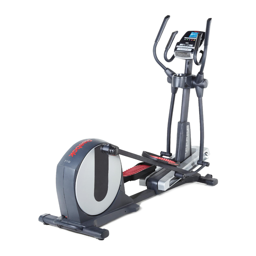
www.reebokfitness.com
Model No. RBEL07913.0
USER’'S MANUAL
Serial No.
Write the serial number in the space
above for reference.
Serial Number
Decal (under frame)
ACTIVATE YOUR
WARRANTY
To register your product and
activate your warranty today,
go to www.reebokservice.com/
registration.
CUSTOMER CARE
For service at any time, go to
www.reebokservice.com.
Or call 1-877-994-4999
Mon.––Fri. 6 a.m.––6 p.m. MT
Sat. 8 a.m.––4 p.m. MT
Please do not contact the store.
CAUTION
Read all precautions and instruc-
tions in this manual before using
this equipment. Keep this manual
for future reference.
Advertisement
Table of Contents

Related Manuals for Reebok 710 Elliptical


Summary of Contents for Reebok 710 Elliptical
- Page 1 www.reebokfitness.com Model No. RBEL07913.0 USER’’S MANUAL Serial No. Write the serial number in the space above for reference. Serial Number Decal (under frame) ACTIVATE YOUR WARRANTY To register your product and activate your warranty today, go to www.reebokservice.com/ registration. CUSTOMER CARE For service at any time, go to www.reebokservice.com.
-
Page 2: Table Of Contents
Apply the decal in the loca- tion shown. Note: The decal(s) may not be shown at actual size. REEBOK and the Vector Logo are registered trademarks and service marks of Reebok. This product is manufactured and distributed under license from Reebok International. -
Page 3: Important Precautions
IMPORTANT PRECAUTIONS WARNING: To reduce the risk of burns, fire, electric shock, or injury to persons, read all important precautions and instructions in this manual and all warnings on your elliptical before using your elliptical. ICON assumes no responsibility for personal injury or property damage sus- tained by or through the use of this product. - Page 5 STANDARD SERVICE PLANS...
-
Page 6: Before You Begin
Thank you for selecting the revolutionary REEBOK ® manual. To help us assist you, note the product model 710 elliptical. The 710 elliptical provides an impressive number and serial number before contacting us. The selection of features designed to make your workouts model number and the location of the serial number at home more effective and enjoyable. -
Page 7: Part Identification Chart
PART IDENTIFICATION CHART Use the drawings below to identify the small parts needed for assembly. The number in parentheses below each drawing is the key number of the part, from the PART LIST near the end of this manual. The number following the key number is the quantity needed for assembly. -
Page 8: Assembly
ASSEMBLY •• To hire an authorized service technician to •• To identify small parts, see page 7. assemble this product, call 1-800-445-2480. •• In addition to the included tool(s), assembly •• Assembly requires two persons. requires the following tools: one Phillips screwdriver ••... - Page 9 3. Orient the Front Stabilizer (3) as shown. While a second person lifts the front of the Frame (1), attach the Front Stabilizer (3) with two M10 x 120mm Screws (100). 4. Identify and orient the Upright (5) and the Top Cover (23) as shown.
- Page 10 5. Identify the Right Upper Body Arm (8) and the Right Upper Body Leg (6) and orient them as shown. Insert the Right Upper Body Arm (8) into the Right Upper Body Leg (6). Attach the Right Upper Body Arm (8) with three M8 x 45mm Bolts (104) and three M8 Locknuts (105).
- Page 11 7. Note: The Leveling Foot (41) may be preattached. With the help of a second person, place some of the packaging materials (not shown) under the Frame (1). Have the second person hold the Frame to prevent it from tipping while you complete this step.
- Page 12 9. See the upper drawing. Locate the Ramp Roller (92) on the Right Pedal Arm (12). Set the Ramp Roller (92) on the right side of the Ramp (43). See the lower drawing. Pull upward on the Latch (117) on the Right Pedal Arm (12). Press the Right Pedal Arm (12) onto the right Sleeve (136).
- Page 13 11. Apply grease to a Link Arm Axle (94) and to an M17 Wave Washer (88). First, insert the Link Arm Axle (94) into the Right Upper Body Leg (6) from the side shown. Next, slide the M17 Wave Washer (88) onto the Link Arm Axle.
- Page 14 13. Tip: Avoid pinching the wires. Attach the Rear Upright Cover (24) to the Upright (5) with four M4 x 16mm Screws (93). Tip: It may be necessary Avoid pinching the wires to bend the upper end of the Rear Upright Cover gently into place around the Upright.
- Page 15 16. Identify the Right Rear Leg Cover (29). Attach the Right Rear Leg Cover (29) around the Right Upper Body Arm (8) by pressing it into the Right Front Leg Cover (30). Repeat this step on the other side of the elliptical.
- Page 16 18. Have a second person hold the Handlebar (10) near the Upright (5). See the inset drawing. Locate the Pulse Wire (135) in the Handlebar (10). Insert the Pulse Wire into the front of the Upright (5) and pull it out of the hole in the Upright as shown.
- Page 17 20. While a second person holds the Console (33) near the Handlebar (10), connect the wires on the Console to the Upright Wire (60) and to the Pulse Wire (135). Avoid pinching the wires Insert the excess wire into the Handlebar (10) or into the Console (33).
-
Page 18: How To Use The Elliptical
HOW TO USE THE ELLIPTICAL HOW TO PLUG IN THE POWER CORD A temporary adapter may 2-pole Receptacle This product must be grounded. If it should malfunc- be used to tion or break down, grounding provides a path of least connect the Adapter resistance for electric current to reduce the risk of... - Page 19 HOW TO FOLD AND UNFOLD THE ELLIPTICAL HOW TO MOVE THE ELLIPTICAL When the ellipti- To move the elliptical, first fold it as described at cal is not in use, the left. Next, stand in front of the elliptical, hold the the frame can upright, and place one foot against one of the wheels.
- Page 20 HOW TO EXERCISE ON THE ELLIPTICAL To dismount the elliptical, wait until the pedals come to a complete stop. Note: The elliptical does not have To mount the elliptical, hold the upper body arms and a free wheel; the pedals will continue to move until step onto the pedal that is in the lowest position.
- Page 21 CONSOLE DIAGRAM FEATURES OF THE CONSOLE The advanced console offers an array of features designed to make your workouts more effective and enjoyable. When you use the manual mode of the console, you can change the resistance of the pedals and the incline of the ramp with the touch of a button.
- Page 22 HOW TO TURN ON THE POWER 3. Change the resistance of the pedals and the incline of the ramp as desired. IMPORTANT: If the elliptical has been exposed to cold temperatures, allow it to warm to room tem- As you pedal, change the resistance of the pedals perature before turning on the power.
- Page 23 Incline——This display mode will show the incline Calorie——This tab will show the approximate level of the ramp for a few seconds each time the amount of calories you have burned. The height of incline level changes. each segment represents the amount of calories burned during that segment.
- Page 24 5. Measure your heart rate if desired. 6. Turn on the fan if desired. If there are The fan has low and sheets of plas- high speed settings. Contacts tic on the metal Press the fan increase contacts on the and decrease buttons handgrip heart repeatedly to select a fan speed or to turn off the...
- Page 25 HOW TO USE AN ONBOARD WORKOUT resistance level, ramp incline level, and/or target rpm is programmed for the next segment, the resis- 1. Begin pedaling or press any button on the tance level, ramp incline level, and/or target rpm console to turn on the console. will appear in the display for a few seconds to alert you.
- Page 26 HOW TO USE A SET-A-GOAL WORKOUT Note: The calorie goal is an estimate of the number of calories that you will burn during 1. Begin pedaling or press any button on the the workout. The actual number of calories that console to turn on the console.
- Page 27 HOW TO USE AN IFIT WORKOUT To compete in a race that you have previously scheduled, press the Compete button. You must have an iFit module to use an iFit workout. To re-run a recent iFit workout from your sched- To purchase an iFit module at any time, go to ule, first press the Track button.
- Page 28 6. Follow your progress with the display. HOW TO USE THE SOUND SYSTEM See step 4 on page 22. To play music or audio books through the console sound system while you exercise, plug your audio The My Trail tab will show a map of the trail you are cable into the jack on the console and into a jack on walking or running or it will show a track and the your MP3 player or CD player;...
- Page 29 HOW TO CHANGE CONSOLE SETTINGS If no module is connected, the display will show the words NO IFIT MODULE. If no module is con- The console features a user mode that allows you to nected, go to step 10. view usage information, select a unit of measurement, and adjust the contrast level of the display.
-
Page 30: Fcc Information
FCC INFORMATION This equipment has been tested and found to comply with the limits for a Class B digital device, pursuant to part 15 of the FCC Rules. These limits are designed to provide reasonable protection against harmful interference in a residential installation. This equipment generates, uses, and can radiate radio frequency energy and, if not installed and used in accordance with the instructions, may cause harmful interference to radio communications. -
Page 31: Maintenance And Troubleshooting
MAINTENANCE AND TROUBLESHOOTING Inspect and tighten all parts of the elliptical regularly. HOW TO ADJUST THE REED SWITCH Replace any worn parts immediately. If the console does not display correct feedback, the To clean the elliptical, use a damp cloth and a small reed switch should be adjusted. - Page 32 HOW TO ADJUST THE DRIVE BELT See EXPLODED DRAWING B on page 37. Remove the M4 x 16mm Screws (93) and the M4 x 42mm If you can feel the pedals slip while you are pedaling, Screws (124) from the Right and Left Shields (18, 19). even when the resistance is adjusted to the highest Make sure to note which size Screws come from level, the drive belt may need to be adjusted.
-
Page 33: Exercise Guidelines
EXERCISE GUIDELINES Burning Fat——To burn fat effectively, you must exer- WARNING: cise at a low intensity level for a sustained period of Before beginning this time. During the first few minutes of exercise, your or any exercise program, consult your physi- body uses carbohydrate calories for energy. -
Page 34: Part List
PART LIST Model No. RBEL07913.0 R0113A Key No. Qty. Description Key No. Qty. Description Frame Left Lift Arm Folding Frame Lift Axle Bushing Front Stabilizer Long Motor Axle Rear Stabilizer Short Motor Axle Upright Bumper Right Upper Body Leg #8 x 25mm Self-tapping Screw Left Upper Body Leg Upright Bushing Right Upper Body Arm... - Page 35 Key No. Qty. Description Key No. Qty. Description Anchored Zip Tie M8 x 25mm x 1.5mm Washer M8 x 16mm Screw M8 x 30mm Screw M10 Locknut M8 x 25mm Screw M8 x 45mm Bolt Outer Sleeve Bushing M8 Locknut Small Snap Ring Link Arm Bushing M8 Split Washer...
-
Page 36: Exploded Drawing
EXPLODED DRAWING A Model No. RBEL07913.0 R0113A... - Page 37 EXPLODED DRAWING B Model No. RBEL07913.0 R0113A...
- Page 38 EXPLODED DRAWING C Model No. RBEL07913.0 R0113A...
- Page 39 EXPLODED DRAWING D Model No. RBEL07913.0 R0113A...
- Page 40 ORDERING REPLACEMENT PARTS To order replacement parts, please see the front cover of this manual. To help us assist you, be prepared to provide the following information when contacting us: •• the model number and serial number of the product (see the front cover of this manual) ••...
Need help?
Do you have a question about the 710 Elliptical and is the answer not in the manual?
Questions and answers