Ariston microGENUS 23 MFFI Installation Instructions Manual
Type c boilers
Hide thumbs
Also See for microGENUS 23 MFFI:
- User manual (24 pages) ,
- Servicing instructions (28 pages) ,
- Servicing instructions (28 pages)

Related Manuals for Ariston microGENUS 23 MFFI


Summary of Contents for Ariston microGENUS 23 MFFI
- Page 1 Installation Instructions Type C Boilers G.C.N: 47-116-14 47-116-15 LEAVE THESE INSTRUCTIONS WITH THE END-USER Country of destination: GB...
-
Page 2: Table Of Contents
TABLE OF CONTENTS GENERAL INFORMATION 1.1 G ENERAL NSTRUCTIONS 1.2 O VERALL INSTALLATION 2.1 R EFERENCE TANDARDS 2.2 S ITING THE PPLIANCE 2.3 O VERALL IMENSIONS 2.4 C LEARANCES 2.5 M OUNTING THE PPLIANCE 2.6 E LECTRICAL ONNECTION 2.7 G ONNECTION 2.8 W ATER... - Page 3 This manual is an integral and essential part of the product. It should be kept GENERAL with the appliance so that it can be consulted by the user and our authorised INFORMATION personnel. Please carefully read the instructions and notices about the unit contained in this manual, as they provide important infor mation regarding the safe installation, use and maintenance of...
- Page 4 5 - If called for by point. 3, dismantling and cleaning of the combustion chamber. 6 - If called for by point. 4, dismantling and cleaning of the burner jets. 7 - Visual check of the primary heat exchanger: check for overheating in the blade assembly; clean the exhaust fan if needed.
-
Page 5: R Eference S Tandards
The technical information and instructions provided herein below are INSTALLATION intended for the installer so that the unit may be installed correctly and safely. The installation and initial start up of the boiler must be by a CORGI EFERENCE TANDARDS Approved Installer in compliance with the installation standards currently in effect, as well as with any and all local health and safety standards i.e.. -
Page 6: C Learances
VERALL IMENSIONS EGEND A = Central Heating Flow (3/4”) B = Domestic Hot Water Outlet (1/2”) C = Gas Inlet (3/4”) D = Domestic Cold Water Inlet (1/2”) E = Central Heating Return (3/4”) LEARANCES In order to allow for access to the interior of the boiler for maintenance pur poses, the boiler must be installed in compliance with the minimum clearances indicated in F . - Page 7 marked “L”. Note: The diagrams for the electrical system are indicated in section 2.11. Warning, this appliance must be earthed. External wiring to the appliance must be carried out by a qualified technician and be in accordance with the current I.E.E. Regulations and applicable local regulations.
- Page 8 Copper tubing to BS EN 1057:1996 is recommended for water pipes. Jointing should be either with capillary soldered or compression fittings. Where possible pipes should have a gradient to ensure air is carried naturally to air release points and water flows naturally to drain taps. The appliance has a built-in automatic air release valve, however it should be ensured as far as possible that the appliance heat exchanger is not a natural collecting point for air.
- Page 9 YSTEM ONNECTIONS The provision for satisfactory flue termination must be made as described in BS 5440-1. The appliance must be installed so that the flue terminal is exposed to outdoor air. The terminal must not discharge into another room or space such as an outhouse or lean-to.
- Page 10 In addition, it is also possible to use a split (twin pipe) system by fitting a special adaptor to the flue connector and using the aperture for the air vent intake located on the top part of the combustion chamber. To utilise the air intake it is necessary to: 1.
- Page 11 23 MFFI ABLE Exhaust Restrictor Maximum Risk of Condensation Forming Type ø 43 mm Restrictor Extension Piping insulated Piping not insulated Exhaust/Air ø 43 ø 43 restrictor restrictor C12 (xx) Coaxial L min = 0.5 m L min = 2 m L = 4 m NONE NONE...
- Page 12 In calculating the lengths of the pipes, the maximum length “L” must also take into consideration values YSTEMS exhaust/air intake end terminals, as well as 90° elbows for coaxial systems. The C52 types must comply with the following requirements: 1 - The exhaust/ air intake pipes must have the same diameter of 80 mm.
- Page 13 2.12 LECTRICAL IAGRAM Circulation Pump EGEND Spark Generator/Gas Valve Supply = Time Clock Connector Motorised Diverter Valve = Central Heating Selection (Winter) and Flame Detection Circuit Temperature Adjustment Detection Electrode = Connector for Total Check System Main Circuit Temperature Probe = Domestic Hot Water Temperature Adjustment Domestic Hot Water Temperature Probe = Soft-light Adjustment...
- Page 14 . 2.13 SF014A 2.13 ATER IRCUIT IAGRAM EGEND . 2.14 Main Heat Exchanger Overheat Thermostat Burner Ignition Electrodes Detection Electrode Motorised Valve Main Circuit Temperature Probe Main Circuit Flow Switch 10. Automatic By-pass 11. Domestic Hot Water Temperature Probe 12. Secondary Heat Exchanger 13.
- Page 15 COMMISSIONING MTS (GB) Limited support the initiative. Within the information pack NITIAL REPARATION you will find a copy of the logbook. It is important that this is completed in the presence of your customer, they are shown how to us it, and it is signed by them.
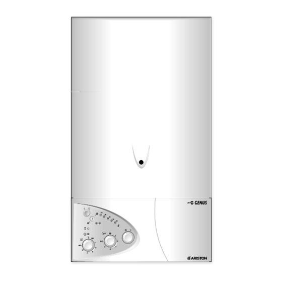
- Page 16 ONTROL ANEL EGEND A - On/Off knob B - Domestic hot water temperature adjustment knob C - Central heating selection (winter) and temperature adjustment knob D - On/Off L.E.D. (green) E - Fume sensor L.E.D. (yellow) F - Ignition failure (lockout) L.E.D. (red) G - “Economy/Comfort”...
- Page 17 HE CHECKS TO BE RUN BEFORE INITIAL START UP ARE AS FOLLOWS 3.4. I NITIAL TART 1. Make sure that: - the screw on the automatic air valve has been loosened when the system is full; - If the water pressure in the system is below 1 bar, bring it up to the appropriate level;...
- Page 18 readings can be The flue connector has two apertures, OMBUSTION NALYSIS taken for the temperature of the combustion by-products and of the combustion air, as well as of the concentrations of O and CO , etc. To access these intakes it is necessary to unscrew the front screw and remove the metal plate with sealing gasket.
- Page 19 5. A FROST DEVICE The boiler is equipped with a device that, in the event of the water temperature going below 5°C, the 3-way diverter valve switches to domestic hot water and the burner ignites at the minimum power until the boiler water reaches a temperature of about 50°C.
-
Page 20: Gas Adjustments
GAS ADJUSTMENTS Liquid Butane Gas Liquid Propane Gas CATEGORY II2H3+ Methane Gas MJ/m 3 h Lower Wobbe Index (15°C;1013mbar) 45.67 80.58 80.58 Nominal Delivery Pressure mbar Minimum Delivery Pressure mbar 23 MFFI Main Burner: n. 13 jets (ø) 1.30 0.77 0.77 Consumption (15°C;... -
Page 21: W Ater C Onnections
MAINTENANCE It is recommended that the following inspections be carried out on the boiler at least once a year: 1 - Check the seals for the water connections; replacement of any faulty seals. 2 - Check the gas seals; replacement of any faulty gas seals. 3 - Visual check of the entire unit. -
Page 22: Control Panel
MISCELLANEOUS IRING IAGRAM FOR EATING ONES BROWN BOILER ELECTRICAL SUPPLY CABLE BLUE GREY ORANGE Remove internal time clock plug from the the P.C.B. then connect GREEN/YELLOW TYPICAL room stat terminal block on the JUNCTION BOX V4043H reverse of the boiler control panel VALVE (see section 2.10) to 9 + 10 on •... - Page 23 IRING IAGRAM FOR ONNECTION TO AN RISTON NVENTED YLINDER BOILER ELECTRICAL SUPPLY CABLE Remove internal time clock plug T6360B from the the P.C.B. then connect ROOM TYPICAL room stat terminal block on the THERMOSTAT JUNCTION BOX reverse of the boiler control panel BROWN (see section 2.10) to 9 + 10 on •...
-
Page 24: Technical Information
TECHNICAL INFORMATION 23 MFFI 27 MFFI CE Certification 63AU4549 63AU4549 Heat Input max/min kW 25.6/11.0 29.8/12.0 Heat Output max/min kW Efficiency of Nominal Heat Input 92.9 93.5 Efficiency at 30% of Nominal Heat Input 91.1 90.7 Heat Loss to the Casing ( T=50°C) Flue Heat Loss with Burner Operating Flue Heat Loss with Burner Off Maximum Discharge of Fumes (G20)
Need help?
Do you have a question about the microGENUS 23 MFFI and is the answer not in the manual?
Questions and answers