Sign In
Upload
Download
Table of Contents
Contents
Add to my manuals
Delete from my manuals
Share
URL of this page:
HTML Link:
Bookmark this page
Add
Manual will be automatically added to "My Manuals"
Print this page
×
Bookmark added
×
Added to my manuals
Manuals
Brands
Foxconn Manuals
Motherboard
R10-A1
User manual
Foxconn R10-A1 User Manual
Ahd1s series motherboard
Hide thumbs
1
2
3
4
5
Table Of Contents
6
7
8
9
10
11
12
13
14
15
16
17
18
19
20
21
22
23
24
25
26
27
28
29
30
31
32
33
34
35
36
37
38
39
40
41
42
page
of
42
Go
/
42
Contents
Table of Contents
Bookmarks
Table of Contents
Symbol Description
Declaration of Conformity
Installation Precautions
Table of Contents
Chapter 1 Product Introduction
Product Specifications
Layout
Back Panel Connectors
Chapter 2 Installation
Install the Memory
Install an Expansion Card
Install Other Internal Connectors
Jumpers
Install Driver and Utility
Install Driver
Chapter 3 Bios Setup
Enter BIOS Setup
Main
Advanced
Cpu Configuration
Sata Configuration
Usb Configuration
Legacy Usb Support
Super Io Configuration
Serial Port
Device Settings
Change Settings
Onboard Device Configuration
Onboard Lan Controller
Chipset
Boot
Power
Health
Security
Save & Exit
Restore Defaults
Advertisement
Quick Links
1
Symbol Description
2
Product Specifications
3
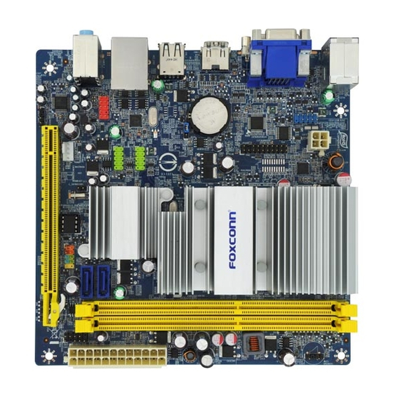
Layout
4
Install the Memory
5
Install Other Internal Connectors
6
Jumpers
Download this manual
AHD1S Series
Motherboard
User's Manual
Table of
Contents
Previous
Page
Next
Page
1
2
3
4
5
Advertisement
Table of Contents
Need help?
Do you have a question about the R10-A1 and is the answer not in the manual?
Ask a question
Questions and answers
Related Manuals for Foxconn R10-A1
Motherboard Foxconn R10-H1 User Manual
H67s series motherboard (73 pages)
Motherboard Foxconn Rattler User Manual
User manual (111 pages)
Motherboard Foxconn Renaissance II Manual
Easyguide. (2 pages)
Motherboard Foxconn Renaissance User Manual
English manual. (122 pages)
Motherboard Foxconn 45CMX User Manual
Motherboards 45cmx/45gmx series (73 pages)
Motherboard Foxconn A78AX-K User Manual
English manual. (106 pages)
Motherboard Foxconn 945GZ7MC User Manual
Foxconn 945gz7mc motherboard user manual (29 pages)
Motherboard Foxconn P9657AA Manual
(66 pages)
Motherboard Foxconn M61PMV Series User Manual
English manual. (108 pages)
Motherboard Foxconn H61MXP Series User Manual
User manual (70 pages)
Motherboard Foxconn G31MX User Manual
Multi language manual. (47 pages)
Motherboard Foxconn P55MX Series User Manual
English manual. (111 pages)
Motherboard Foxconn H61MX Series User Manual
User manual (72 pages)
Motherboard Foxconn H61MXE Series User Manual
User manual (66 pages)
Motherboard Foxconn G31MV-K User Manual
English manual. (77 pages)
Motherboard Foxconn G31MXP User Manual
G31mxp series (78 pages)
This manual is also suitable for:
R20-a1
R30-a1
R40-a1
R50-a1
Ahd1s
Ahd1s-k
Table of Contents
Print
Rename the bookmark
Delete bookmark?
Delete from my manuals?
Login
Sign In
OR
Sign in with Facebook
Sign in with Google
Upload manual
Upload from disk
Upload from URL


Need help?
Do you have a question about the R10-A1 and is the answer not in the manual?
Questions and answers