Table of Contents
Advertisement
Quick Links
(1) SDU5500 Index
1
Index ............................................................................................ 1
1-1
Introduction .................................................................................. 1
1-2
Taking care of the unit .................................................................. 2
1-3
Power requirements ..................................................................... 2
1-4
Operating anomalies .................................................................... 2
1-5
Accessories supplied .................................................................... 2
1-6
Technical high-lights ..................................................................... 3
2
Controls and connections .......................................................... 4
2-1
Front panel controls ...................................................................... 4
2-2
Rear Panel ................................................................................... 5
3
LCD, keys, legends & menus ..................................................... 6
3-1
Description of LCD legends .......................................................... 6
3-2
SDU5500 menu overview ............................................................. 10
3-3
Important considerations .............................................................. 14
3-3-1
LCD resolution ............................................................................. 14
3-3-2
Significance of receive STEP size ................................................ 14
3-3-3
Significance of RBW (Resolution Band Width) ............................. 15
4
Making the SDU5500 ready for operation ................................. 15
4-1
Configuration of the AR5000 companion radio ............................. 15
4-2
Configuration of the AR3000A companion radio ........................... 17
4-3
Configuration of an ICOM companion radio .................................. 19
4-3-1
Example set-up for the ICOM IC-R7100 receiver ......................... 20
4-3-2
Example set-up for the ICOM IC-R8500 receiver .......................... 20
4-4
Operation with an "Other" companion receiver ............................. 21
5
General operation of the SDU5500 ............................................ 23
5-1
Using the SDU5500... sequence to use ........................................ 23
5-2
Spectrum analyser mode .............................................................. 28
5-3
Step resolution mode ................................................................... 30
5-4
Channel scope mode ................................................................... 33
5-5
Passive bandscope operation ...................................................... 36
6
Special considerations .............................................................. 37
7
Computer control information ................................................... 38
8
Specification ............................................................................... 42
1-1 Introduction
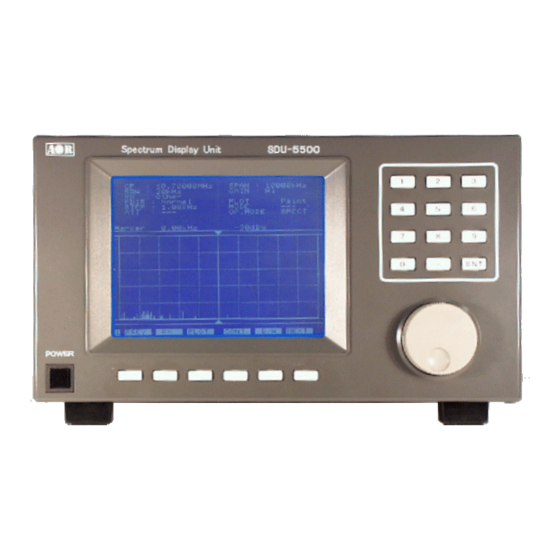
Thank you for purchasing the SDU5500 Spectrum Display Unit. For years AOR has been marketing the
worlds' first colour spectrum display unit SDU5000 for professionals and the top-end of hobbyist
listeners. The SDU5500 is a worthy successor to the SDU5000, using a large high resolution LCD
display (similar to high priced dedicated spectrum analysers) backed by the latest microprocessor
technology to ensure high versatility and reliability. To get the best possible results, we recommended
that you read this manual to fully familiarise yourself with the SDU5500.
Every effort has been made to make this manual correct and up to date. Due to continuous
development of the product and by error or omission, anomalies may be found and this is
acknowledged.
© This manual is protected by copyright AOR Ltd 1999. No information contained in this manual may be
copied or transferred by any means without the prior written consent of AOR Ltd. AOR and the
AOR logo are trade marks of AOR Ltd. All other trade marks and names are acknowledged.
Section 1, 1-1
E&OE
1
Advertisement
Table of Contents

Related Manuals for AOR SDU5500


Summary of Contents for AOR SDU5500
-
Page 1: Table Of Contents
© This manual is protected by copyright AOR Ltd 1999. No information contained in this manual may be copied or transferred by any means without the prior written consent of AOR Ltd. AOR and the AOR logo are trade marks of AOR Ltd. -
Page 2: Taking Care Of The Unit
Do not use or leave the SDU5500 in direct sunlight (especially the LCD). It is best to avoid locations where excessive heat, humidity, dust and vibration are expected. Always keep the SDU5500 free from dust and moisture. -
Page 3: Technical High-Lights
Any companion radio receiver which is equipped with a 10.7MHz IF output may be used with the SDU5500. It is possible to use a companion receiver with an IF not of 10.7 MHz but within the range of 5.7 to 15.7 MHz by reprogramming the IF frequency employed by the SDU5500, however In order to provide a useful bandwidth of at least 1 MHz (+/- 500kHz), as a rule of thumb, the limits of IF should be considered as 6.7 to 14.7 MHz. -
Page 4: Controls And Connections
The entry of centre-frequency (receive frequency) is via the ten keys which are labelled plus decimal and enter 6 Bail bar A tilt bail bar is provided under the front panel (on the bottom case half) so that the SDU5500 may be tilted upward at the front to improve visibility in certain installations. -
Page 5: Rear Panel
2 RX CTR (receiver connection socket) The supplied 9-way to 9-way ‘D-type’ male to male lead is used to connect the SDU5500 to the AR5000 receiver. If used with another receiver, a suitable serial-adapter or connecting cable will be required. -
Page 6: Lcd, Keys, Legends & Menus
(avoid null modem leads, these will not operate): SDU5500 9-pin PC 9-pin PC 25-pin 7 GND The SDU5500 is fully controllable by PC via the built-in RS232 interface, this includes all keyboard operations and down loading of the displayed data. Communication parameter Data length 8 bit... - Page 7 Section 3-1 Middle, graphical display The middle section of the LCD is mapped into a graticule of ten boxes horizontally and five boxes high. The horizontal scale is determined by the SPAN (see later under LCD resolution). The vertical scale is calibrated in 10dBm increments ranging from: •...
- Page 8 SDU5500 input gain The input stage of the SDU5500 has two gain settings Hi / Low, this is selectable from menu 2. Input gain is measured at the input of the SDU5500, not at the companion radio aerial socket. The difference between high and low gain setting is about 30dB.
- Page 9 “Peak” is displayed when peak hold is activated, the maximum strength of incoming signals will be frozen on the LCD until the peak facility is disengaged (finishing the current session) or SDU5500 switched off. The spin wheel dial may be used to hop between peaks in order of amplitude.
-
Page 10: Sdu5500 Menu Overview
3-2 SDU5500 menu overview Operation of the SDU5500 is controlled by seven menus numbered 1 to 7. The menu number is always displayed in the bottom left of the LCD, even when information is being keyed. The radio type is defined in menu 1. - Page 11 STEP Companion radio tuning step size in kHz. (not available in channel scope mode) Toggles the companion radio attenuator on/off (not available in ‘Other’ radio operation) GAIN Toggles the SDU5500 gain between Hi and Low NEXT Move to next menu...
- Page 12 Section 3-2 3 3 3 3 3 Menu 3 PREV Move to previous menu SPECT Places the SDU5500 into spectrum analyser mode (default) STRES Step resolution mode CHANL Channel scope mode (not available in ‘Other’ radio operation) NEXT Move to next menu...
- Page 13 Section 3-2 6 6 6 6 6 Menu 6 PREV Move to previous menu When “MAX” is selected, the maximum height of traces are frozen on the display. This will result in ‘peaks’ where transmissions have taken place, one side effect is that the baseline will tend to build-up a 5 to 10dB solid bar due to random background noise.
-
Page 14: Important Considerations
‘approximate’ frequency only... especially as the total span width is increased above 1 MHz or so. However, if an appropriate step size has been set, the SDU5500 / companion radio will automatically calculate the ‘likely’ exact frequency when the MK-CF (marker to centre frequency) key is pressed. -
Page 15: Significance Of Rbw (Resolution Band Width)
3-3-3 Significance of RBW (Resolution Band Width) RBW sets the SDU5500 input filter and ‘sampling’ rate, either 5 kHz or 30 kHz. Selection of 30 kHz will provide a faster trace update, 10 MHz being swept in about two seconds... sampling every 30 kHz. - Page 16 Once the SDU5500 has been configured for the AR5000 companion radio following a cold start (or any other receiver in use), it will not be necessary to enter the receiver details again as long as the SDU5500 remains connected to power (presuming that you wish to continue using the same receiver type)... even after the SDU5500 has been switched off and back on again.
-
Page 17: Configuration Of The Ar3000A Companion Radio
Should you prefer to operate the AR5000 from it’s own front panel, it is possible to configure the SDU5500 for “Other’ companion radio and use the display unit as a band scope only. The Centre Frequency will then always be displayed as 10.7 MHz but an OFFSET will be displayed making the measurement of interesting traces possible. - Page 18 / make up a suitable lead (see section 2-2 item 2 of this manual for pin-out information). • Connect a 50 OHM BNC patch lead between the RF IN socket of the SDU5500 and the IF OUT socket of the AR3000A (following modification of the receiver).
-
Page 19: Configuration Of An Icom Companion Radio
All controls of the AR3000A will be locked while in REMOTE mode. The minimum specified tuning step size when used with the SDU5500 is 50 Hz , any digits below 50 Hz will be ignored, the acceptable step sizes being in the range 50 Hz to 999.95 kHz inclusive. -
Page 20: Example Set-Up For The Icom Ic-R7100 Receiver
IC-R9000, connect and power the optional ICOM CT17 interface. • Connect a 50 OHM patch lead between the RF IN socket of the SDU5500 and the IF OUT socket of the receiver (ICOM use a phono socket, the input of the SDU5500 uses a BNC). -
Page 21: Operation With An "Other" Companion Receiver
The RX CTR socket of the SDU5500 is not used as direct control of the companion radio’s controls is not possible. • Connect a 50 OHM patch lead between the RF IN BNC socket of the SDU5500 and the IF OUT socket of the companion radio. •... - Page 22 It is possible to use a companion radio with an IF not of 10.7 MHz but within the range of 5.7 to 15.7 MHz by reprogramming the IF frequency employed by the SDU5500 to a resolution of tens of Hz.
-
Page 23: General Operation Of The Sdu5500
Section 5, 5-1 (5) General operation of the SDU5500 There are effectively two methods of operation when companion radios are connected to the SDU5500: Active mode, the radio is controlled from the SDU5500 in SPECTRUM, STEP RESOLUTION or CHANNEL SCOPE mode. - Page 24 If you wish to toggle the SDU5500 input gain, press GAIN This affects the gain of the SDU5500 and has no effect on the sensitivity of the companion radio. The base line of the SDU5500 is equivalent to -40dBm in HIGH and -10dBm in LOW. The legend “GAIN” confirms the status of gain setting.
- Page 25 Section 5-1 The receive frequency is NOT the centre frequency of display but is equal to the START frequency, a pair of ‘outline triangle legends’ (above and below the graphical start frequency) indicate the receive frequency. CHANL mode is confirmed by the legend “OP.MODE : CHANL” on the LCD. To return to a standard spectrum analyser display press SPECT Reprogramming channel scope mode: Next time channel scope mode is used, the previous parameters will be employed unless they are redefined using the “FREQ”...
- Page 26 To select a standard marker display mode rather than ‘peak’ or ‘continuous peak’ press MKR ... this is the selection by default. (i.e. returns the SDU5500 to ‘marker’ mode if ‘PEAK’ or ‘CPEAK’ have been selected). The LCD legend “Marker” is displayed directly above the LCD graticule to confirm operation.
- Page 27 Section 5-1 Note: If [MK-CF] is used with the companion radio set to “Other”, the IF frequency employed will be changed from the default of 10.7 MHz. In normal use, this should be avoided, however this may be useful if the exact centre frequency of the companion radio is not known. Select menu 6...
-
Page 28: Spectrum Analyser Mode
Section 5-2 5-2 Spectrum analyser mode The standard default mode used by the SDU5500 is spectrum analyser mode “SPECT”. As an example of usage, monitor the FM broadcast band using spectrum analyser mode with the AR5000. 1) Connect the AR5000 with the SDU5500 referring to section 4-1 of this operating manual. - Page 29 10000kHz (10 MHz) using kHz format Leave the RBW set to 30 kHz. (Ensure that the SDU5500 gain control is set to “High”, menu 2). The LCD should be displaying a centre frequency of 95 MHz with a spread of 5 MHz on either side (the screen representing 90 MHz to 100 MHz from left to right).
-
Page 30: Step Resolution Mode
As an example of usage, monitor the FM broadcast band using step resolution mode with the AR5000. 1) Connect the AR5000 with the SDU5500 referring to the section 4-1 of this operating manual. First switch on the AR5000 then the SDU5500. Unless... - Page 31 The message “AR5000 Connected” will be briefly displayed on the SDU5500, if an error message “RX Disconnected” appears, re-check the connections and the RS232 parameters of the AR5000 (the SDU5500 may try two or three times to connect to the AR5000).
- Page 32 Section 5-3 Push the CF key and enter the required centre frequency in MHz format. In this example select 95 MHz followed by The LCD legend “CF : 95.00000MHz” confirms entry. Leave the RBW set to 30 kHz. 6) Go to menu 5, if necessary use the PREV NEXT keys or press the numeric key This menu is used to define the operation of the frequency marker.
-
Page 33: Channel Scope Mode
As an example of usage, monitor a small section of the VHF airband using channel scope mode with the AR5000. 1) Connect the AR5000 with the SDU5500 referring to section 4-1 of this manual. First switch on the AR5000 then the SDU5500. Unless the AR5000/SDU5500 combination has been previously configured,... - Page 34 Rotate the spin wheel dial to highlight “AR5000” then press . The message “AR5000 Connected” will be briefly displayed on the SDU5500, if an error message “RX Disconnected” appears, re-check the connections and the RS232 parameters of the AR5000 (the SDU5500 may try two or three times to connect to the AR5000).
- Page 35 “RF” which is default to the lower frequency of 120 MHz in this example. The span is automatically set by the SDU5500 with the spectrum trace displayed either side of the centre point, in this example the span width is 4050 kHz (4.05 MHz).
-
Page 36: Passive Bandscope Operation
To measure active frequencies, simply add or subtract the marker offset from the frequency displayed on the companion radio. For example: If the companion radio display is 88.300 MHz and the SDU5500 offset is displaying +4407.89kHz, the actual frequency will be 88.300 + 4.40789 = 92.70789 MHz As VHF Band-II is allocated in 100kHz increments, the true frequency is 92.700 MHz... -
Page 37: Special Considerations
You are reminded of the following points: Displayed signal level The signal level which the SDU5500 provides is always at the RF input of the SDU5500, not the signal level at the companion radio aerial input. -
Page 38: Computer Control Information
PC enabling recording of activity and historic analysis. The SDU5500 is equipped with an RS232 port in addition to the connection port for a companion radio. The two connectors are the same, please refer to section 2-2 of this manual to assist with identification. - Page 39 Section 7 WVPM2 RSCF RVPM SCF84.30000 VPM2 The second example uses Windows HyperTerminal, Plot mode is set to outline “WVPM2”, plot mode is read to confirm the command “RVPM” and the response to the request is displayed “VPM2”: S = Spectrum analysis Function Read/Write Command category...
- Page 40 Section 7 V = Visual command Function Read/Write Command category Type of command Parameter Example Response PLOT MODE SET 1=PAINT 2=OUTLINE WVPM1 [CR] + or ? PLOT MODE READ RVPM [CR] VPM1 + FDIR SET 1=NORMAL 2=REVERSE WVDD1 [CR] + or ? FDIR READ RVDD [CR] VDD1 +...
- Page 41 + or ? CH MODE MKER READ R RURF [CR] URF84.30000 + I = Information The following table is used only during production of the SDU5500 to assist testing, the commands are given for completeness only. Function Read/Write Command category...
-
Page 42: Specification
Section 8 (8) Specification Model SDU5500 Input Frequency 10.7 MHz Sweep Width 1 kHz to 10 MHz (1 kHz step) Frequency Accuracy ± 600 Hz Resolution Bandwidth 5/30 kHz Reference Level -10, -40dBm Maximum Input Level -10dBm Dynamic Range 50dBm min Level Accuracy Linearity within ±...
Need help?
Do you have a question about the SDU5500 and is the answer not in the manual?
Questions and answers