Advertisement
Table of Contents
- 1 Owners Manual
- 2 Specifications
- 3 Table of Contents
- 4 Step-By-Step Installation
- 5 LCD Display / Buttons
- 6 Selecting the Temperature Unit (°C or °F)
- 7 Selecting the Heat Cycle Rate
- 8 Adjusting the Desired Set Temperature
- 9 Heating Power Level Display
- 10 Troubleshooting
- 11 Limited 2-Year Warranty
- Download this manual
Advertisement
Table of Contents

Related Manuals for Dimplex HTC521W


Summary of Contents for Dimplex HTC521W
-
Page 1: Owners Manual
Owners Manual HTC521W Non-Programmable Thermostat 3600W HTC525W Non-Programmable Thermostat 4000W 7213100100R01... -
Page 2: Specifications
Congratulations on your purchase of this Dimplex line-voltage thermostat. Your new ther- mostat is preprogrammed by the installer and ready to use. Please take the time to read and understand this manual so you can begin to enjoy the convenience this product offers. -
Page 3: Table Of Contents
Limited 2-Year Warranty ........13 Contact us at: www.dimplex.com/customer_support For Troubleshooting and Technical Support Toll-Free 1-888-DIMPLEX (1-888-346-7539) Monday to Friday 8:00 a.m. to 4:30 p.m. EST Please have your model number and product serial number ready. - Page 4 Installation This product is for use with high voltage system (120V~240V) with a minimum load of 300W; it is not designed for use with low voltage (24V) central heating & air conditioning systems or wall mounted furnaces. In order to avoid fire, shock or death, shut off power supply at the circuit breaker or fuse and test that the power is off before wiring. This product must be installed in accordance with the Canadian Electri- cal Code, and in the province of Quebec, by a qualified electrician. Dim- plex assumes no responsibility for damages caused by improper wiring.
-
Page 5: Step-By-Step Installation
Installation Step-by-step Installation Remove the old thermostat carefully and identify the two wires from the wall box. Gently remove the faceplate from the right side of the new thermostat. Note: Do not remove the screws from the back of the unit as these screws hold the ther- mostat together. - Page 6 Installation Step-by-step Installation . . . continued *120V ~ 240V AC Lines Mount the new thermostat onto the wall box using the two screws provided through the mounting holes, and then replace the faceplate. (Place 2 screws in the right side or 2 left holes).
-
Page 7: Lcd Display / Buttons
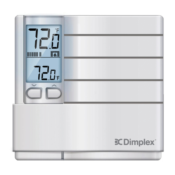
Operation LCD Display / Buttons ❷ ❶ ❹ ❸ ❺ LCD Display Location of Buttons ❶ Current Temperature A Down Button ❷ Temperature Unit (°C or °F) B Up Button ❸ Heating Power Level ❹ Heat “On” Indicator ❺ Set Temperature... -
Page 8: Selecting The Temperature Unit (°C Or °F)
Operation Selecting the Temperature Unit (°C or °F) This thermostat features an adjustable display setting that can display the temperature in either Celsius or Fahrenheit. • To enter the setting mode, press the UP and DOWN buttons at the same time for 3 seconds. - Page 9 Operation Selecting the Heat Cycle Rate . . . continued While it is still in the Setting mode, press the DOWN button to toggle between the various CYCLE RATES. There are 3 different cycle rates to choose from: Cycle Rates Cr-0 OFF (fixed span) Cr-1...
-
Page 10: Adjusting The Desired Set Temperature
Operation Adjusting the Desired Set Temperature The current /room temperature (A) is normally displayed on the LCD screen. To adjust the setting to the desired set temperature, press the UP (C) or DOWN (B) button. • The temperature can be set in increments of 0.5°C or 0.5°F. • The temperature setting range is from 5°C to 35°C (41°F to 95°F.) Tip: Press and hold the UP or DOWN button to change the setting more rapidly. -
Page 11: Heating Power Level Display
Operation Heating Power Level Display When the thermostat activates the heating system, the Heat “On” symbol will ap- pear. Equipped with an intelligent proportional regulation system, this thermostat will deter- mine the amount of power needed by the electric heater to maintain the room temperature at precisely the set temperature. -
Page 12: Troubleshooting
Troubleshooting Problem Solution The LCD screen is blank or • Make sure the thermostat is fully installed. abnormal • Check that the power supply has been reconnected at the circuit breaker or fuse. • If the heater or heating appliance has a power switch of its own, check to see that it is in the ON position. -
Page 13: Limited 2-Year Warranty
This product, excluding battery, comes with a two-year (2) warranty against manufac- turer's defects in workmanship and material. The warranty allows for repair or replacement product at Dimplex’s discretion. Dimplex accepts no liability for labour related costs. (Note: Shipping and handling charges are not included under this warranty).
Need help?
Do you have a question about the HTC521W and is the answer not in the manual?
Questions and answers