Table of Contents
Advertisement
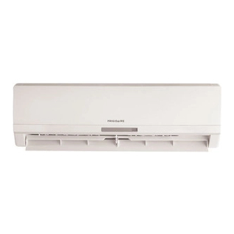
All about the
Installation
of your
Split Type Room Air Conditioner
w
w
w
r f .
g i
d i
a
r i
. e
o c
m
U
S
A
1
8 -
6
6
9 -
4
2
1 -
5
6
7
w
Model(indoor/outdoor):
FRS09PYW1/FRS09PYC1
FRS12PYW1/FRS12PYC1
FRS184YW2/FRS184YC2
FRS18PYW2/FRS18PYC2
FRS224YW2/FRS224YC2
FRS22PYW2/FRS22PYC2
w
w
r f .
g i
d i
a
r i
. e
a c
C
a
n
a
d
a
1
8 -
6
6
9 -
4
2
1 -
5
6
7
Advertisement
Table of Contents


Need help?
Do you have a question about the FRS09PYW1 and is the answer not in the manual?
Questions and answers